The electric submersible motor is simple in construction, rugged and reliable. In this article, the ESP motor compounds are detailed as well as their main functions.
Introduction to ESP motor:
- ESP motor is installed below the motor seal and above the downhole sensor. In cases where a downhole sensor is not installed, the motor is installed at the very bottom of ESP string, generally attached to a motor guide.
- ESP motor is an induction motor, two poles, three phases, squirrel cage type stator winding filled with specific motor oil, high dielectric strength (> 28 KV). The motor is rated for a specific horsepower, voltage, & current. Its role is to drive the downhole pump and seal section.
- The ESP motor rotates at approximately 3500 RPM at 60 Hertz. The difference between actual and the synchronous speed (3,600 RPM) is called “motor slippage” and it is due to losses inside the motor. The actual RPM is usually noted on the motor nameplate (example: 3500 RPM / 60 Hz – 2917 RPM / 50 Hz).
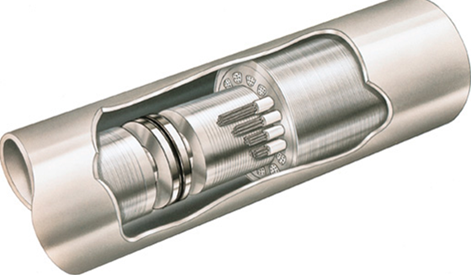
- The ESP motor is constructed of rotors and bearings stacked on the shaft and loaded in a wound stator, the motor compounds will be detailed in the next section.
- The motor contains synthetic dielectric mineral oil for lubrication, insulation, and for the homogeneous distribution of the heat generated inside the motor (cooling). Heat is then drawn off by the produced fluid past the housing OD on the way to the intake.
NB: ESP motor is close to the same design type as motors used on beam pumping units. Of course, it must be small in diameter in order to fit inside oil well casing sizes.
The ESP motor compounds:
-
The Stator (the stationary part/ static):
The stator is the core or electrical field of the motor. It is composed of the housing material for the desired diameter, the stator core, and the stator windings (as per the graph below).
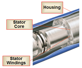
- The housing material forms the cover for the motor and is threaded at both ends for head and base components. The housing can be of different diameters and its material can be chosen for different applications, depending upon the environment.
- The stator core is composed of laminations stacked under pressure to insure a permanently tight core. Laminations are thin sheets of die-punched steel or bronze material (refer to the below photo).
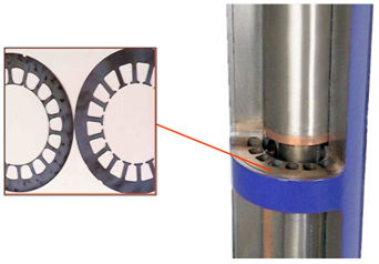
- The stator windings are made from either Polyimide or PEEK material, for primary magnetizing winding wound through the die-punched slots in the stator core.
-
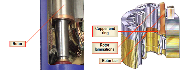
The Rotor (the moving part/ rotate):
The rotor is a device that rotates inside of the stator core. The rotor is made up of rotor laminations that are smaller in diameter from the stator laminations and these create the iron core. Inside each slot are copper bars with supporting copper end rings. Because the structure resembles the cage used to exercise squirrels, rotors of this type are called “Squirrel-Cage rotors”.
- Rotor Bearings are one of the most vital parts of the motor. There are fluid holes to insure oil circulation and wide angle oil grooves on the OD to distribute lubrication evenly over the entire length of the bearing surface.
-
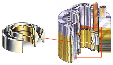
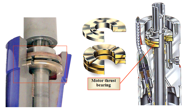
The Motor Thrust Bearing:
The motor thrust bearing is installed at the top of the rotor string. It is designed to hold the weight of the entire rotor string. There are several types of motor thrust bearings. The thrust bearing limits will indicate the type of load required for the selected bearing material.
-
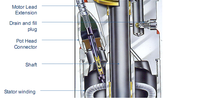
The Pothead:
The pothead is a key part to connect the motor with the power cable; its mechanical and end sealing ensure the long-term operation of the motor.
You May Also Like…
- Submersible Pump System Overview
- Pump Intake
- ESP: Gas handling device
- Motor Seal
- ESP Cable
- ESP Motor Switchboard
- Variable Frequency Drive Basics
- Introduction to transformer: How it works?
- Wellhead Equipment for ESP
- ESP Accessory Equipment