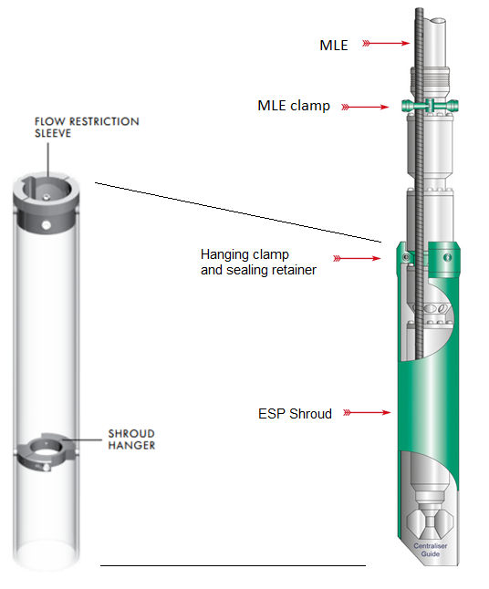
The ESP motor Shroud is a cylinder fitted around the Motor, Protector and Intake sections of an ESP. It is designed to provide cooling to the motor when fluid velocities are below minimum by reducing the annular area between the ESP and the casing bore.
The Shroud is simply constructed with a length of tube long enough to swallow the Motor, Protector and Intake sections, and is bolted with a split clamp unit to first ESP neck located above Intake. The MLE cable is run through the shroud. The shroud assembly is made up of a jacket (a length of casing or pipe), a hanging clamp and sealing retainer for the top, and a centralizer for the bottom.
Above the Shroud, an MLE Clamp is normally fitted to secure the MLE to the Discharge Head. At the bottom end, a Centralizer Guide is fitted to help secure the ESP section within the Shroud. The Shroud can be manufactured from a thin casing, stainless steel or fiberglass.
Applications:
- Low flow velocity ESP System applications
- Pump setting below the perforations
- Large bore wells
- Onshore and Offshore wells
- Subsea or Deepwater production
Configuration:
The most commonly used shroud configuration is when the ESP is set below perforations and the shroud directs the production flow down and back up by the motor for cooling. The purpose of setting below perforations is to increase the production rate for the same pump intake pressure or to serve as a simple reverse flow gas separation.
Shroud Selection Criteria:
Shroud Length: It is selected on the basis of shroud location relative to the production zone and the function of the shroud. However, at a minimum, the shroud be fitted around the pump intake, the seal and the motor of the ESP.
Shroud ID: It has to permit the insertion of the motor, seal and pump intake with a flow clearance to allow for proper motor cooling velocities without excessive pressure drop to the flow.
Shroud OD: it must have sufficient clearance with the casing ID to ensure reliable deployment and proper flow in the annular space (shroud/casing) from the producing zone to the pump intake.
You May Also Like…
- Submersible Pump System Overview
- Pump Intake
- ESP: Gas handling device
- Motor Seal
- ESP Motor
- ESP Cable
- ESP Motor Switchboard
- Variable Frequency Drive Basics
- Introduction to transformer: How it works?
- Wellhead Equipment for ESP
- ESP Accessory Equipment