


Casing is the major structural component of a well. It is a tubular steel product used to line the wellbore (maintain borehole stability), prevent contamination of water sands, isolate water from producing formations, and control well pressures during drilling, production, and workover operations. Casing provides locations for the installation of blowout preventers, wellhead equipment, production packers, and production tubing.
The cost of casing is a major part of the overall well cost, so the selection of casing size, grade, connectors, and setting depth is a primary engineering and economic consideration.
Casing Strings:
Since the well is normally drilled in segments, multiple concentric casing strings are usually installed in the well. There are six basic types of casing strings:
Conductor Casing:
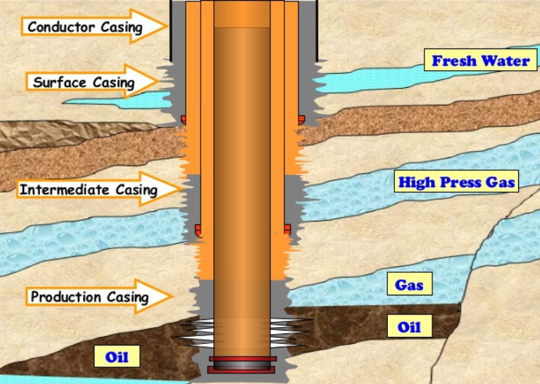
The first casing installed in the well is called the conductor casing, as shown in the figure below. Onshore this is a short segment usually around 60 ft (20 m) long. The conductor isolates unconsolidated formations and water sands and protects against shallow gas. This is usually the string onto which the casing head is installed. Conductor casing is always cemented to surface.
Surface Casing:
Surface casing must be set deep enough to protect freshwater aquifers from contamination, and prevent lost circulation. Because of this, the surface casing is always cemented to surface. Surface casing depths typically vary between 1000 and 3000 ft (300-900 m).
Intermediate Casing:
Intermediate casing is set to isolate unstable hole sections, lost-circulation zones, low-pressure zones, and production zones. It is often set in the transition zone from normal to abnormal pressure. The casing cement top must isolate any hydrocarbon zones.
Some wells require multiple intermediate strings and some other wells do not have intermediate casing string.
Production Casing:
Production casing is used to isolate production zones and contain formation pressures. It may also be exposed to injection pressures from fracture jobs, gas lift, or water injection support. A good primary cement job is very critical for this string.
Liner:
Liner is a casing string that does not extend back to the wellhead but instead is hung from another casing string. Liners are used instead of full casing strings to reduce cost, improve hydraulic performance when drilling deeper, allow the use of larger tubing above the liner top, and not represent a tension limitation for a rig. Liners can be either an intermediate or a production string. Liners are typically cemented over their entire length.
Tieback String:
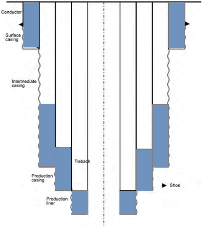
Tieback string is a casing string that provides additional pressure integrity from the liner top to the wellhead. An intermediate tieback is used to isolate a casing string that cannot withstand possible pressure loads if drilling is continued (usually because of excessive wear or higher than anticipated pressures). Similarly, a production tieback isolates an intermediate string from production loads. Tiebacks can be uncemented or partially cemented.
An example of a typical casing program that illustrates each of the specified casing string types is shown in the following figure.
Typical Casing Combination Strings:
A typical casing combination casing strings for a mature water-flooded field might be:
- 13-3/8″ (340 mm) Conductor
- 9-5/8″ (244 mm) Surface Casing
- 7″ (178 mm) Production Casing
For a deeper, higher pressured well a typical casing string might be:
- 16″ (406 mm) Conductor
- 13-3/8″ (340 mm) Surface Casing
- 9-5/8″ (244 mm) Intermediate Casing
- 7″ (178 mm) Production Casing
- 4-1/2″ (114 mm) Production Liner
Casing Specifications:
Casing is specified by grade, outer diameter (in or mm), nominal weight (lb/ft or kg/m) and connection type.
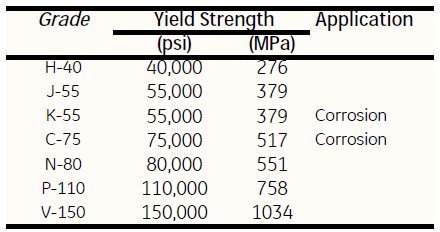
Steel Grade:
The grade reflects the material composition and yield strength of the casing material. API casing grades are listed in the table below:
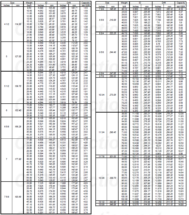
Nominal Weight:
Nominal weight is the average linear weight of the tubing, connection included. It is expressed in lb/ft or kg/m and it determines the tubing wall thickness that in turn determines the nominal inner diameter.
Length:
Casing usually comes in lengths between 40 and 46 ft (12-14 m).
Inner Diameter:
Because the inner diameter is nominal, a guaranteed inner diameter called the drift diameter is also specified. The drift diameter is typically 1/8″ (3.2 mm) less than the nominal inner diameter. Equipment with a larger diameter than the drift diameter should not be run into a well.
Connection Type:
The connection is the type of thread used to connect the joints of casing. API thread types are short thread (STC), long thread (LTC), buttress and extreme line. A number of proprietary premium casing threads are also available.
Standards for Tubulars:
- API Bull 5C2, Performance Properties of Casing, Tubing, and Drill Pipe.
- API TR 5C3, Technical Report on Equations and Calculations for Casing, Tubing, and Line Pipe Used as Casing or Tubing; and Performance Properties Tables for Casing and Tubing.
- API Spec 5CT, Specification for Casing and Tubing.
- ISO 11960, Petroleum and natural gas industries –Steel pipes for use as casing or tubing for wells.
- ISO 11961, Petroleum and natural gas industries –Steel drill pipe.
- ISO 13679, Petroleum and natural gas industries –Procedures for testing casing and tubing connections.
You May Also Like…
