


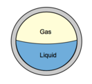
For oil wells, the main component of pressure loss is the gravity or hydrostatic term. Calculation of the hydrostatic pressure loss requires knowledge of the proportion of the pipe occupied by liquid (holdup) and the densities of the liquid and gas phases. Accurate modeling of fluid PVT properties is essential to obtain in-situ gas/liquid proportions, phase densities, and viscosities.
Calculation of holdup is complicated by the phenomenon of gas/liquid slip. Gas, being less dense than liquid flows with a greater vertical velocity than liquid. The difference in velocity between the gas and liquid is termed the slip velocity. The effect of slip is to increase the mixture density and hence the gravity pressure gradient.
In the next paragraphs, two-phase flow properties (holdup, densities, velocity, and viscosity) will be detailed. Then the pressure gradient equation which is applicable to any fluid flowing in a pipe inclined at an angle φ is depicted. As well as, the two-phase flow procedure to calculate the outlet pressure is detailed.
Two-Phase Flow Properties:
Holdup:
With reference to multiphase flow in pipes, the fraction of a particular fluid present in an interval of a pipe. In multiphase flow, each fluid moves at a different speed due to different gravitational forces and other factors, with the heavier phase moving slower, or being more held up, than the lighter phase. The holdup of a particular fluid is not the same as the proportion of the total flow rate due to that fluid, also known as its ”cut”. To determine in-situ flow rates, it is necessary to measure the holdup and velocity of each fluid. The sum of the holdups of the fluids present is unity.
1- Liquid and Gas Holdup (HL & Hg):
HL is defined as the ratio of the volume of a pipe segment occupied by the liquid to the volume of the pipe segment. The remainder of the pipe segment is of course occupied by gas, which is referred to as Hg.
Hg = 1 – HL
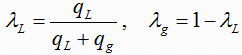
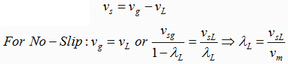
2- No-Slip Liquid and Gas Holdup (λL & λg):
The No-Slip correlation assumes homogeneous flow with no slippage between the phases. Fluid properties are
taken as the average of the gas and liquid phases and friction factors are calculated using the single phase
Moody correlation.
λL is defined as the ratio of the volume of the liquid in a pipe segment divided by the volume of the pipe segment which would exist if the gas and liquid traveled at the same velocity (no-slippage). It can be calculated directly from the known gas and liquid volumetric flow rates from :
Density:
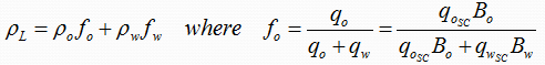
1- Liquid Density (ρL):
ρL may be calculated from the oil and water densities with the assumption of no slippage between the oil and water phases as follows:
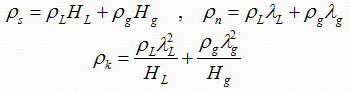
2- Two-Phase Density:
Calculation of the two-phase density requires knowledge of the liquid holdup. Three equations for two-phase density are used by various investigators in two-phase flow:
Velocity:
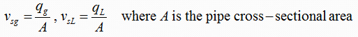
1- Superficial Gas and Liquid Velocities (vsg & vsL):
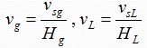
2- Actual Gas and Liquid Velocities (vg & vL):
3- Two-Phase Velocity (vm):
![]()
4- Slip Velocity (vs):
Viscosity:
1- Liquid Viscosity (μL):
μL may be calculated from the oil and water viscosities with the assumption of no slippage between the oil and water phases as follows:
![]()
2- Two-Phase Viscosity:
Calculation of the two-phase viscosity requires knowledge of the liquid holdup. Two equations for two-phase viscosity are used by various investigators in two-phase flow:
![]()
3- Liquid Surface Tension (σL):
![]()
General Pressure Gradient Equation:
The pressure gradient equation which is applicable to any fluid flowing in a pipe inclined at an angle φ from horizontal was derived previously. This equation is usually adapted for two-phase flow by assuming that the two-phase flow regime and two-phase properties can be considered homogeneous over a finite volume of the pipe.
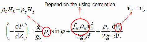
Many correlations have been developed for predicting two-phase flow pressure gradients which differ in the manner used to calculate the three terms of pressure gradients equation (elevation change, friction, and acceleration terms):
a. No slip, no flow regime considerations: the mixture density is calculated based on the no slip holdup. No distinction is made for different flow regimes.
b. Slip considered, no flow regime consideration: The same correlations for liquid holdup and friction factor are used for all flow regimes.
c. Slip considered, flow regime considered: Usually a different liquid holdup and friction factor prediction methods are required in each flow regimes.
Two-Phase Flow Procedure for Outlet Pressure Calculation:
- Starting with the known inlet pressure and flow rates.
- Select a length increment, ΔL, and estimate the pressure drop in this increment, ΔP.
- Calculate the average pressure and, for non-isothermal cases, the average temperature in the increment.
- Determine the gas and liquid properties (based on black-oil or compositional model) at average pressure and temperature conditions.
- Calculate the pressure gradient, dP/dL, in the increment at average conditions of pressure, temperature, and pipe inclination, using the appropriate pressure gradient correlation.
- Calculate the pressure drop in the selected length increment, ΔP=ΔL(-dP/dL).
- Compare the estimated and calculated values of ΔP. If they are not sufficiently close, estimate a new value and return to step 3.
- Repeat the steps 2 to 7 for the next pipe length increment.
Flow Correlation Information
Multi-phase flow correlations are used to predict the liquid holdup and frictional pressure gradient. Correlations in common use consider liquid/gas interactions – the oil and water are lumped together as one equivalent fluid. They are therefore more correctly termed two-phase flow correlations. Depending on the particular correlation, flow regimes are identified and specialized holdup and friction gradient calculations are applied for each flow regime.
There is no universal rule for selecting the best flow correlation for a given application. It is recommended that a Correlation Comparison always be carried out. By inspecting the predicted flow regimes and pressure results, the User can select the correlation that best models the physical situation.
Reference:
You May Also Like…
- Well Inflow Performance
- Introduction to IPR and VLP
- Vogel’s inflow performance relationship
- The Composite Inflow Performance Relationship
- Pressure Gradient
- Pressure drawdown & Skin Factor
- Multiphase flow regimes
- Multiphase flow correlations
