Pressure loss calculations through a conduit

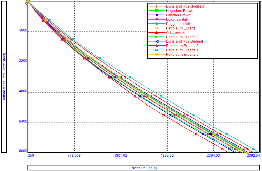
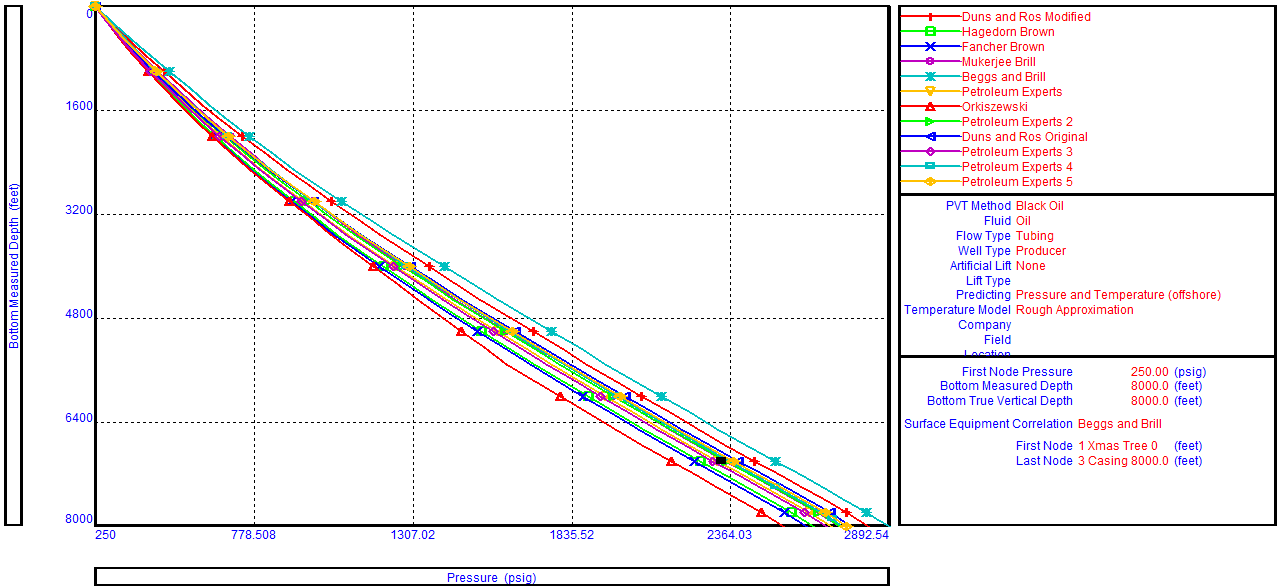
Whenever a fluid flows through a conduit pressure loss occurs. Many methods are available to calculate frictional pressure losses. They range from simple empirical equations to rigorous mechanistic multiphase flow models.

Darcy-Weisbach flow equation:

The Darcy-Weisbach flow equation is theoretically sound equation derived from the Conservation of Mass and Conservation of Momentum laws. Named after Henry Darcy and Julius Weisbach, it relates the pressure loss due to friction along a given length of pipe to the average velocity of the fluid flow for an incompressible fluid.

The Darcy-Weisbach equation contains a dimensionless friction factor, known as the Darcy friction factor. This is also variously called the Darcy–Weisbach friction factor, friction factor, resistance coefficient, flow coefficient, or Moody friction factor.

In a cylindrical pipe of uniform hydraulic diameter d, flowing full, the pressure loss due to density and viscous effects dp/dL is proportional to length L and can be characterized by the Darcy–Weisbach equation:

Where:

  • dP/dL = Pressure Gradient (psi/ft)
  • f = friction factor
  • ρ = Fluid density (lb/ft3)
  • v = Fluid velocity (ft/s))
  • d = Hydraulic diameter (ft))

The equation can be written as shown below in both typical US oilfield units and SI units:

Continue reading

Multiphase correlations References

Multiphase correlations References:

Correlation Description Reference
1 Anand, et al Predicting Thermal Conductivities of Formations from Other Known Properties. JPT (Oct. 1980).
2 Ashford, F.E, & Pierce, P.E. The Determination of Multiphase Pressure Drops and Flow Capacities in Downhole Safety Valves (Storm Chokes). SPE 5161 1974 SPE Annual Fall Meeting, Houston Oct. 6-9.
3 Beggs, H.D. & Brill, J.P. A Study of Two Phase Flow in Inclined Pipe. JPT (May 1973), 606-617.
4 Churchill-Chu Correlating Equations for Laminar and Turbulent Free Convection from a Horizontal Cylinder. International Journal Heat Mass Transfer (1975) 18, 1049-1053.
5 Fancher, & Brown, G.G. Prediction of Pressure Gradients for Multiphase Flow in Tubing. SPE Journal (Mar. 1963), 59-64.
6 Fortunati Two Phase Flow Through Well-head Chokes. SPE 3742 1972 SPE European Spring Meeting, Amsterdam, May 17-18.
7 Hagedorn, A.R. & Brown, K.E. Experimental Study of Pressure Gradients Occurring During Continuous Two-Phase Flow in Small-Diameter Vertical Conduits. JPT (Apr. 1965), 475-484.
8 Mandhane et al A Flow Pattern Map for Gas-liquid Flow in Horizontal Pipes. International Journal Multiphase Flow, 1, 537-541.
9 Moody Friction Factor for Pipe Flow. Trans., AIME (1944), 66, 671-675.
10 Mukherjee, H. & Brill, J.P. Liquid Holdup Correlations for Inclined Two-Phase Flow. JPT (May 1983), 1003-1008.
11 Oranje Condensate Behaviour in Gas Pipeline is Predictable. Oil and Gas Journal (July 1973), 39-43.
12 Orkiszewski Predicting Two Phase Pressure Drop in Vertical Pipes. JPT (June 1967), 829-833.
13 Duns, H. Jr & Ros, N.C.J. Vertical Flow of Gas and Liquid Mixtures in Wells. Proc., Sixth World Petroleum Congress, Frankfurt (1963) 451.
14 Tansev, E. Startzman, R. & Cooper, A. Predicting Pressure Loss and Heat Transfer in Geothermal Wellbores. SPE 5584 1975 SPE Annual Fall Meeting, Dallas, Sept. 28-Oct. 1.
15 Gould, T.L, Tek, M.R. & Katz, D.L. Two-Phase Flow Through Vertical, Inclined, or Curved Pipe. JPT, August, 1974, 915-925.

Reference: PROSPER Use’s Guide.

Continue reading

Outflow Performance Correlation Selection

There is no universal rule for selecting the best flow correlation for a given application. When an outflow performance simulator is used, it is recommended that a Correlation Comparison always be carried out. By inspecting the predicted flow regimes and pressure results, the User can select the correlation that best models the physical situation. Refer to the article titled “Multiphase flow correlations” for more details about flow correlations and their use.

Fancher and Brown is a no-slip correlation, with no flow regime map. Therefore, this correlation cannot be recommended for general use and should not be used for quantitative work. on the other hand, Duns and Ros Modified gives the highest pressure drops in the slug flow regime for oil wells. This is why Fancher Brown (no slip) and Duns and Ros Modified can serve only as quality check boundaries for downhole measurements.

Continue reading

Multiphase flow correlations

The primary purpose of a multiphase flow correlations is to predict the liquid holdup (and hence the flowing mixture density) and the frictional pressure gradient.  This article details the most widely used correlations for the prediction of the Vertical Lift Performance.

The oil and water are lumped together as one equivalent fluid. Thus flow correlations in common use consider liquid/gas interactions.  They are therefore more correctly termed two-phase flow correlations.  Depending on the particular correlation, flow regimes are identified and specialized holdup and friction gradient calculations are applied for each flow regime.

There is no universal rule for selecting the best flow correlation for a given application. When an outflow performance simulator is used, it is recommended that a Correlation Comparison always be carried out. By inspecting the predicted flow regimes and pressure results, the User can select the correlation that best models the physical situation.

Multiphase flow correlations:

Fancher & Brown:

  • Fancher and Brown is a no-slip correlation, with no flow regime map. Therefore, this correlation cannot be recommended for general use and it is provided for use as a quality control (should not be used for quantitative work).
  • It gives the lowest possible value of Vertical lift Performance (VLP). Therefore, Measured data falling to the left of Fancher Brown on the correlation comparison plot indicates a problem with fluid density (i.e PVT) or field pressure data.
  • According to Brown, it is only suitable for 2-3/8 – 2-7/8 inch tubing.
  • It is for GLR less than 5000 scf/bbl and flow rates less than 400 bpd.
  • It has its own friction factor model, which is independent of pipe roughness.

Continue reading

Multiphase Flow Properties & Pressure Gradient Calculation

For oil wells, the main component of pressure loss is the gravity or hydrostatic term.  Calculation of the hydrostatic pressure loss requires knowledge of the proportion of the pipe occupied by liquid (holdup) and the densities of the liquid and gas phases.  Accurate modeling of fluid PVT properties is essential to obtain in-situ gas/liquid proportions, phase densities, and viscosities.

Calculation of holdup is complicated by the phenomenon of gas/liquid slip.  Gas, being less dense than liquid flows with a greater vertical velocity than liquid. The difference in velocity between the gas and liquid is termed the slip velocity.  The effect of slip is to increase the mixture density and hence the gravity pressure gradient.

In the next paragraphs, two-phase flow properties (holdup, densities, velocity, and viscosity) will be detailed. Then the pressure gradient equation which is applicable to any fluid flowing in a pipe inclined at an angle φ is depicted. As well as, the two-phase flow procedure to calculate the outlet pressure is detailed.

Two-Phase Flow Properties:

Holdup:

With reference to multiphase flow in pipes, the fraction of a particular fluid present in an interval of a pipe. In multiphase flow, each fluid moves at a different speed due to different gravitational forces and other factors, with the heavier phase moving slower, or being more held up, than the lighter phase. The holdup of a particular fluid is not the same as the proportion of the total flow rate due to that fluid, also known as its ”cut”. To determine in-situ flow rates, it is necessary to measure the holdup and velocity of each fluid. The sum of the holdups of the fluids present is unity.

1- Liquid and Gas Holdup (HL & Hg):

HL is defined as the ratio of the volume of a pipe segment occupied by the liquid to the volume of the pipe segment. The remainder of the pipe segment is of course occupied by gas, which is referred to as Hg.

Hg = 1 – HL

Continue reading