Basic Steps to Shoot a Liquid Level using TWM

Before detailing the basic steps to shoot a liquid level, this article will present few benefits of the operation. Fluid Level measurements can provide invaluable information to assist anyone that has an interest in both understanding and evaluating well, or reservoir, performance.

When combined with a surface pressure measurement, the fluid depth in a wellbore can be used to calculate the pressure at the sandface, for either a producing or shut-in well status.

Sandface pressure determination is paramount to help evaluate reservoir characteristics and pressure depletion, as well as determining the producing performance of a well.

Continue reading

How to Prevent Pumping Unit Failures due to Overloading

When there is a catastrophic pumping unit failure it is natural to wonder what happened and how this failure could have been prevented. However, the right answer may or may not be simple to find. The following list shows the most common reasons for a failure and how to prevent or minimize its occurrence in the future:

Continue reading

Sucker Rod Pumping Speed Calculation

Sucker-rod pumping units can be operated over a range of pumping speeds. It is expressed in Strokes per Minute (SPM). Obviously, this assumed that the up and down stroke of a unit forms one complete stroke cycle.
Sucker rod pumping speed can be calculated manually using a stopwatch or automatically by the mean of a pump-off controller (POC). This article will detail the manually pumping speed calculation procedure.

Manually Pumping Speed Calculation Procedure:

  • Start the stopwatch at the bottom of the stroke and measure the time it takes for the unit to complete 10 strokes.
  • Stop the stopwatch at the end of the 10 strokes when the PU is back at the bottom of the stroke. Make a note of the number of seconds it took.
  • Convert the number of seconds into minutes (divide by 60).
  • Divide 10 (the number of strokes) by the time in minutes to obtain the pumping speed expressed in strokes per minute (SPM).

Exercise: Calculate the pumping speed of this PU.


Continue reading

Beam Pump Artificial Lift Optimization

This article gives you some good practices and rules of thumb for optimizing beam pump applications. The following topics have been presented:

  • Artificial Lift Optimization – What does it mean?
  • Required information
  • Typical design situations
  • Optimization considerations
  • Simulate / Measure initial conditions
  • Pump condition, structure loading, and gearbox Loading
  • Miscellaneous notes
  • Design Guidelines: Pump Efficiency, Structure Loading, Gearbox Loading
  • Case 1: Increase Capacity
  • Case 2: Size unit for well w/no unit
  • Dialing in your design
  • Unit Sizing “Rules of Thumb”
  • Sucker Rod Design
  • Rod Guides: Snap Ons, Molded Guides

Continue reading

Why Do We Counterbalance Sucker Rod Pumping Units?

A good understanding of counterbalance is vital to the successful operation of surface sucker rod pumping units.  Poor counterbalance practices can cause early failure of the gear reducer gearing and will result in excessive energy cost.

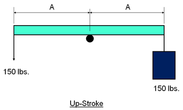
Non-counterbalanced lever system:

The up-stroke:

The figure above represents a simple non-counterbalanced lever system. On the up-stroke, by pulling down on the end of a beam, a man is lifting a bucket full of water having a combined weight of 150 lbs.

Note that the upstroke effort of the man is a substantial 150 lbs.

Continue reading