This article walks through the suggested nine step procedure for selecting and designing an electric submersible pump. This nine step procedure for ESP design is a basic hand-design of simple water and light crude oil. For more complicated well conditions, such as high GOR, viscous oil, high-temperature wells, etc. a number of computer programs are available to automate this process.
Step 1: Basic Data:
As detailed in the article “Step 1: Basic data ”, step 1 of the nine step design procedure is the most important step because all the others design steps will depend on the basic data selected in this step.
In this example, a high water cut well is considered. This is the simplest type of well for sizing submersible equipment.
- Well Profile:
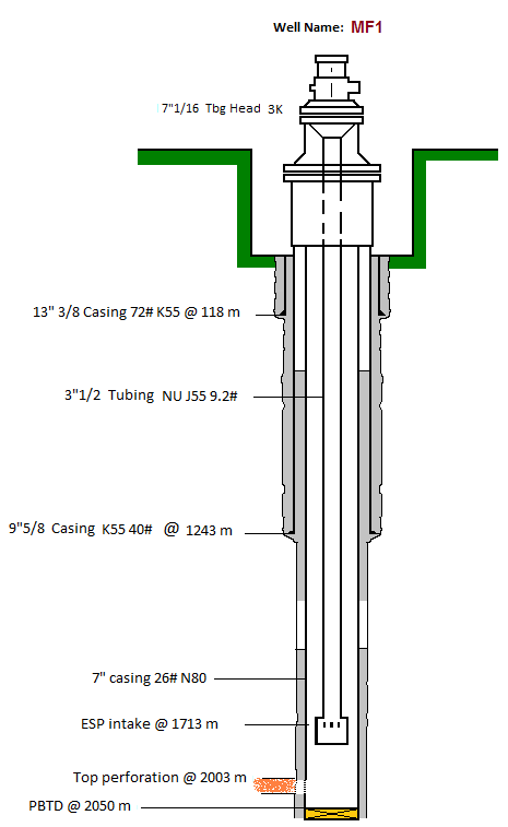
Vertical Well
Casing: 7” 26#
Tubing: 3 ½” 9,2# N80 NU
Top perforation: 2003m
Pump Intake depth: 1713m