Effect of CO2 on downhole flowrate calculation

Downhole flow rate can be calculated from surface flow rate (stock tank barrels) using the following equation. It is assumed that no gas is dissolved in the water phase and the water formation volume factor is equal to one.

Downhole flow rate = [(Oil rate)sc × Bo] + [(Free GOR) × (Oil rate)sc × Gas FVF] + (Water rate)sc

Free GOR = Producing GOR – Solution GOR, therefore:

q = ( Qo × Bo ) + [ ( R – Rs) × Qo × Bg × 1000] + Qw

Where:

  • q = downhole flow rate (bbl/d or m3/d)
  • Qo = Oil flow rate at standard conditions (stb/d or m3sc/d)
  • Bo = Oil formation volume factor (bbl/stb or m3sc/m3sc)
  • R = Producing gas-oil ratio (scf/stb or m3sc/m3sc)
  • Rs = Solution gas-oil ration (scf/stb or m3sc/m3sc)
  • Bg = Gas formation vol. factor (bbl/mscf or m3sc/m3sc)
  • Qw = Water flow rate at standard conditions (stb/d or m3sc/d)

Effect of CO2 on downhole flowrate calculation:

If CO2 is present, the calculation of downhole flow rate becomes more complex for many reasons:

Continue reading

Advantages and Disadvantages of ESP Systems

Advantages & Disadvantages of Electrical Submersible Pumping Systems

From Tables 10-5(a) – 10-5(j), 10-6(a) – 10-6(i), 10-7(a) – 10-7(l)

Artificial Lift Selection, SPE Handbook

Artificial Lift – Design Considerations and Overall Comparisons (Clegg, et al., 12/1993)

Category

Consideration for ESP’s

Capital cost ·    Relatively low capital cost if electric power available. 

·    Costs increase as horsepower increases.

Downhole equipment 
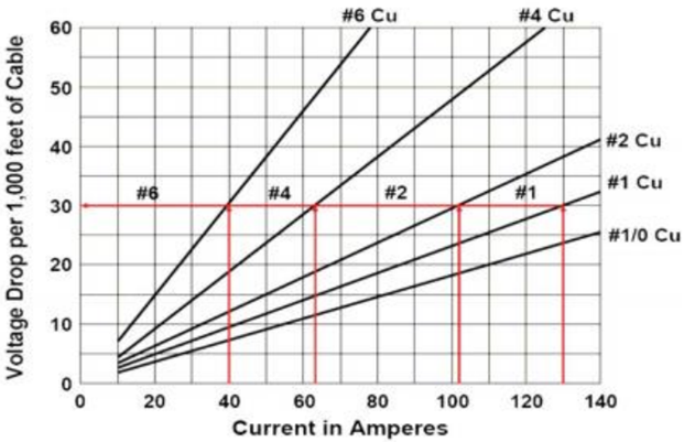
·    Requires proper cable in addition to motor, pumps, seals, etc. 

·    Good design plus good operating practices are essential.


Operating efficiency

(Hydraulic HP/Input HP)

·     Good for high rate wells but decreases significantly for < 1000 BFPD. 

·     Typically total system efficiency is about 50% for high rate wells but for < 1000 BPD, efficiency typically <40%. 

·     Can be as high as 60% for large ID equipment.

Flexibility ·     Poor for fixed speed. 

·     Requires careful design. 

·     VSD provides better flexibility.

Miscellaneous problems ·     Requires a highly reliable electric power system. 

·     System very sensitive to changes downhole or in fluid properties.

Operating costs ·     Varies. 

·     If high HP, high energy costs. 

·     High pulling costs result from short run life especially in offshore operation. 

·     Repair costs often high.

System reliability ·     Varies. 

·     Excellent for ideal lift cases.

·     Poor for problem areas (very sensitive to operating temperatures and electrical malfunctions).

Salvage value ·     Fair. 

·     Some trade in value. 

·     Poor open market values.

System (Total) ·     Fairly simple to design but requires good rate data. 

·     System not forgiving. 

·     Requires excellent operating practices. 

·     Follow API RP’s in design, testing, and operation. 

·     Each well is an individual producer using a common electric system.

Usage/outlook ·     An excellent high rate artificial lift system. 

·     Best suited for <200 0F and >1000 BFPD rates. 

·     Most often used on high water cut wells. 

·     Used on about 5% of US lifted wells.

Casing size limits

(Restricts tubing size)

·     Casing size will limit use of large motors and pumps. 

·     Avoid 4.5” casing and smaller. 

·     Reduced performance inside 5.5” casing depending on depth and rate.

Depth limits ·     Usually limited to motor HP or temperature. 

·     Practical depth about 10,000 feet.

·     1000’ – 10000’ TVD is typical, Max is 15,000 ‘ TVD.

Intake capabilities

(Ability to pump with low pressures at pump intake)

·     Fair if little free gas (i.e. >250 PSI pump intake pressure). 

·     Poor if F = 666*(Qg/Ql)/Pip > 1.0

Where: Pip: intake psi; Qg: gas vol; Ql: liquid vol @ intake conditions.

·     5% gas at low pressures can cause problems.

Noise level ·     Excellent. 

·     Very low noise. 

·     Often preferred in urban areas if production rate high.

Obtrusiveness ·     Good. 

·     Low profile but requires transformer bank.

Prime mover flexibility ·     Fair. 

·     Requires a good power source without spikes or interruptions. 

·     Higher voltages can reduce losses.

Surveillance ·     Fair. 

·     Electrical checks but special equipment needed otherwise.

Relative ease of well testing ·     Good. 

·     Simple with few problems. 

·     High water cut and high rate wells may require a free water knock out (three-phase separator).

Time cycle and pump off controllers application ·     Poor. 

·     Soft start and improved seal/ protectors recommended.

Corrosion/scale handling ability ·     Fair. 

·     Batch treating inhibitor only to intake unless shroud is used.

Crooked/deviated holes ·     Good.

·     Few problems.

·     Limited experience in horizontal wells.

·     Requires long radius wellbore bends to get through.

10° typical,

0 – 90° < 10° / 100 build angle maximum.

·     However must set in section 0 – 2° max deviation.

Duals application ·     No known installations.

·     Larger casing required.

·     Possible run & pull problems.

Gas handling ability ·     Poor for free gas (i.e. >5% through pump).

·     Poor if F = 666 * (Qg/Ql)/Pip > 1.0

Where: Pip: intake psi; Qg: gas vol; Ql: liquid vol, @ intake conditions.

·     Rotary gas separators helpful if solids not produced.

Offshore application ·     Good.

·     Must provide electrical power and service pulling unit.

Paraffin handling capability ·     Fair.

·     Hot water/oil treatments, mechanical cutting, batch inhibition possible.

Slim hole completions

(2 7/8″ tubing, casing)

·     No known installations.
Solids/sand handling ability ·     Poor.

·     Requires <100 – 200 PPM solids for standard construction.

·     200 – 2000 ppm possible with special bushings, stage materials, coatings, and thrust supporting bearings or fixed pumps employed.

·     A maximum of about 5000 ppm might be possible depending on pump and sharpness and angularity of sand.

Temperature limitation ·     Limited to <2500F for standard & <4000F for special motors & cable.

·     100 – 275°F typical.

High viscosity fluid handling capability ·     Fair.

·     Limited to as high as 1000 cp.

·     Depends on economics.   (~>7-9°API)

·     Increases HP and reduces head.

·     Potential solution is to use “core flow” with 20% water.

High volume lift capabilities ·     Excellent.

·     Limited by needed HP and can be restricted by casing size.

·     In 5.5” casing can produce 4000 BFPD from 4000 feet W/240 HP.

·     Tandem motors increase HP & operating costs.

200 – 20,000 bpd typical, ~30,000 bpd max.

52,000 bpd, shallow, 10.25” equip has been done.

Low volume lift capabilities ·      Generally poor.

·      Lower efficiencies and high operating costs <400 BFPD.


Step 9 – Variable Speed Submersible Pumping System

Compared to conventional ESP installations with constant motor speeds, installations running at variable frequencies have several advantages. The most important benefit of a Variable Speed Submersible Pumping System is the wide flexibility of the variable frequency ESP system that permits perfect matching of the lift capacity of the ESP system and the well’s productivity. Therefore, it operates over a much broader range of capacity, head, and efficiency.

NB: Variable Frequency Drive basics (also, named: Variable Speed Drive) are presented and discussed in the article “Variable Frequency Drive Basics”.

Since a submersible pump motor is an induction motor, its speed is proportional to the frequency of the electrical power supply. This relationship between variables involved in pump performance (such as head, flow rate, shaft speed) and power is known as “Affinity Laws” (also called “Pump Laws”).

Continue reading

Step 8 – Downhole and Surface Accessory Equipment

This article “Downhole and Surface Accessory Equipment” is the step 8 of the nine-step procedure to design an ESP with an efficient and cost-effective performance. The required downhole and surface accessory equipment are discussed and recommended practices are highlighted.

Downhole Accessory Equipment:

  • Motor Lead Extension (MLE):

API RP 11S4 defines the Motor Lead Extension as a “special power cable extending from the pothead on the motor to above the end of the pump where it connects with the power cable. A low-profile cable (flat configuration) is usually needed in this area due to limited clearance between the pump housing and the well casing”. It is recommended to select a length at least 6 ft. (1.8 m) longer than the upper end of the pump. The length of MLE has to be select in a way to avoid a splice over a tubing collar. Doing so could allow the cable to catch on the wellbore casing and damage the equipment.

  • Banding Cable Protectors:

Cable protectors are used to protect the Motor Lead Cables from damage during installation, operation and pulling. The figures below show an example of cable protectors.

Continue reading

ESP design – Step 7: Electric Cables

The AC current is carried from the surface to the motor using either copper or aluminum cable conductors. For ESP applications, four sizes of conductors have been standardized: #1, #2, #4 and #6 AWG (AWG stands for “American Wire Gauge”). Electric Cables are available in either flat or round configurations.

An electric submersible cable is mainly compounded by a cable conductor, insulation, jacket, braid & covering and armor. These cable compounds are for protection against corrosive fluids and severe environments.

Cable selection involves the determination of Cable Size, Type and Length.

Cable Size:

The proper cable size is dependent on combined factors of voltage drop, amperage and available space between tubing collars and casing.

  • Cable Voltage Drop:

The following graph shows an example of Cable Voltage drop plot to determine the voltage drop in cable. At the selected motor amperage and the given downhole temperature, the selection of a cable size that will give a voltage drop of less than 30 volts per 1000 feet is recommended. This curve will also enable you to determine the necessary surface voltage (motor voltage plus voltage drop in cable) required to operate the motor.

Continue reading