


This article “Downhole and Surface Accessory Equipment” is the step 8 of the nine-step procedure to design an ESP with an efficient and cost-effective performance. The required downhole and surface accessory equipment are discussed and recommended practices are highlighted.
Downhole Accessory Equipment:
-
Motor Lead Extension (MLE):
API RP 11S4 defines the Motor Lead Extension as a “special power cable extending from the pothead on the motor to above the end of the pump where it connects with the power cable. A low-profile cable (flat configuration) is usually needed in this area due to limited clearance between the pump housing and the well casing”. It is recommended to select a length at least 6 ft. (1.8 m) longer than the upper end of the pump. The length of MLE has to be select in a way to avoid a splice over a tubing collar. Doing so could allow the cable to catch on the wellbore casing and damage the equipment.
-
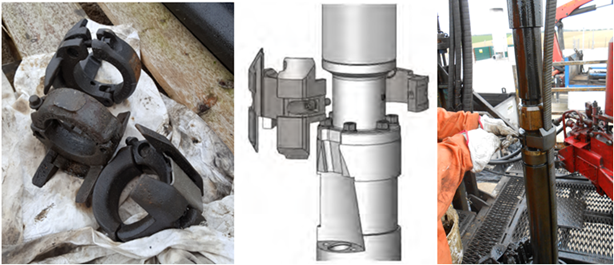
Banding Cable Protectors:
Cable protectors are used to protect the Motor Lead Cables from damage during installation, operation and pulling. The figures below show an example of cable protectors.
-
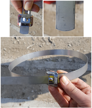
Cable Bands:
Recommended practices related to cable bands and their use:
- Best practice is to install three bands per section from the motor pothead to the first splice in the power cable.
- Do not install bands on a cable splice. Place a band above and below the splice approximately 4 inches.
- The minimum banding recommendation is two bands per tubing joint, with one band in the middle of the joint and the other band 2 to 3 ft above the collar.
- When running through a dogleg or other tight spot in the well, consideration should be given to installing more bands per joint.
- Any application with cable larger than number 4 cable or deeper than 7,000 ft should use three bands per joint of tubing.
-
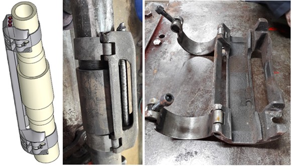
Cross Coupling Cable Protectors:
Cross Coupling Cable Protectors are used to protect and support ESP cable, control lines and injection lines, as well to protect the power cable from damage during installation, operation and pulling.
-
Check Valve:
A check valve is installed about two to three joints above the ESP pump to maintain a full liquid column in the tubing string during equipment shut down periods. This may be desired to eliminate the time it takes to raise the fluid from its static fluid level to the surface (“pump-up time”) or the protective shutdown time for fluid fallback.
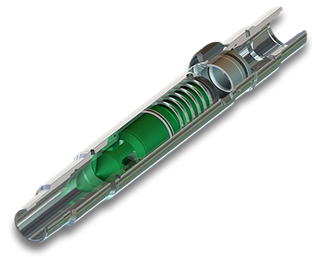
NB: In cases of high GOR wells where gas locking is a possibility, the check valve has to be installed higher than normally, about five to six tubing joints above the ESP pump. Actually, when the ESP shuts down, a gas cap can form under the check valve and be held there by the fluid column above the check valve. If the gas cap volume is large enough to extend down to or below the pump intake, the pump will be immediately gas locked and unable to pump fluids.
Surface Accessory Equipment:
-
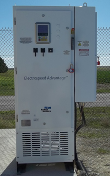
Switchboard / Variable Frequency Drive (VFD):
Compared to conventional ESP installations with constant motor speeds (using a switchboard device), installations running at variable frequencies (using a VFD) have several advantages. The most important benefit is the wide flexibility of the variable frequency ESP system that permits perfect matching of the lift capacity of the ESP system and the well’s productivity.
Variable Frequency Drive basics (also, named: Variable Speed Drive) are presented and discussed in the article “Variable Frequency Drive Basics”.
NB: At this phase of the design the motor has been selected. So that, nameplate voltage is known, and the cable voltage drop has already been calculated.
When specifying switchboards, Variable Frequency Drives and transformers, the most important information is the maximum power of the ESP system required at the surface. This can be found from the Necessary Surface Voltage and the motor current.
Necessary Surface Voltage = Motor’s Nameplate Voltage + Cable Voltage Drop
From the available models, a switchboard/VFD with a rated voltage above this value (the necessary surface voltage) is selected (calculated at the maximum required frequency when VFD is used). The power rating of the switchboard/VFD (in kVA units) is found from the formula used to find three-phase electric power (the total KVA required):
![]()
Where:
Vs is the required surface voltage, volts.
A is the motor nameplate current, amps.
-
Transformers:
In the majority of cases, the available surface voltage is not compatible with the required motor voltage. Therefore, transformers must be used to provide the right voltage level on the surface.
Type of transformers: Single-phase vs. Three-phase:
The type of transformer selected depends on the size of the primary power system and the required secondary voltage. Three-phase isolation step-up transformers are generally selected for increasing voltage from low voltage system, while a bank of three single-phase transformers is usually selected for reducing a high-voltage primary power source to the required surface voltage.
![]()
Transformers are selected on the basis of voltage levels and power ratings. The required surface voltage heavily depends on the setting depth of the ESP equipment since the voltage drop in the power cable increases with cable length. This voltage drop plus the selected motor voltage give the necessary surface voltage.
The necessary three-phase step-up or step-down transformer should have the same kVA rating as the switchboard.
To select the size of a step-up transformer or a bank of three single-phase transformers, the following equation is used to calculate the total KVA required:
![]()
Where:
Vs is the required surface voltage, volts.
A is the motor nameplate current, amps.
NB: How a transformer works and its key components were detailed in the article “Introduction to transformer: How it works? “. Also, refer to the post titled “How to Calculate the Required KVA Rating for three Phase Transformers? ” for more details about KVA rating calculation.
-
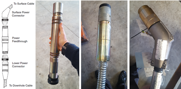
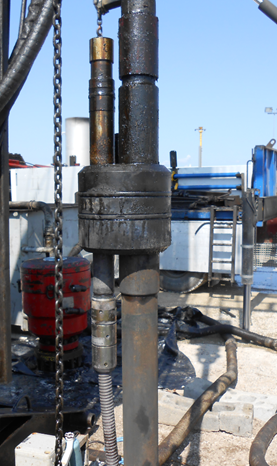
Wellhead Feedthrough, Penetrator, lower and upper pigtails:
The electrical connection of surface and downhole power cables is detailed in figures below. The tubing hanger holds a feed-through mandrel (also called: well penetrator) equipped with the proper seals to contain well pressure and prevent gas leaks at the surface. The power cables are connected to the two ends of this device via their three-phase connectors (also called: lower and upper pigtails).
-
Junction Box:
The power cable coming from the well should be connected to a surface electric cable leading to the switchboard. As seen in the figure below, the two cables are joined in the junction box, also called a “vent box”.
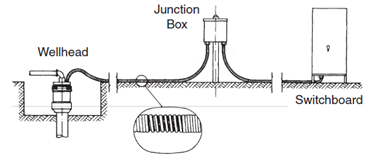
It is a ventilated, weatherproof box performing the following three important functions:
- Provides the electrical connection between the downhole and the surface electric cable.
- Vents any gas to the atmosphere which might reach this point due to migration of well gases up the ESP power cable. The venting of gas eliminates the danger of fire or explosion that could happen if gases travel in the cable to the switchboard.
- Acts as an easily accessible test point for electric checks of the downhole equipment.
