


The AC current is carried from the surface to the motor using either copper or aluminum cable conductors. For ESP applications, four sizes of conductors have been standardized: #1, #2, #4 and #6 AWG (AWG stands for “American Wire Gauge”). Electric Cables are available in either flat or round configurations.
An electric submersible cable is mainly compounded by a cable conductor, insulation, jacket, braid & covering and armor. These cable compounds are for protection against corrosive fluids and severe environments.
Cable selection involves the determination of Cable Size, Type and Length.
Cable Size:
The proper cable size is dependent on combined factors of voltage drop, amperage and available space between tubing collars and casing.
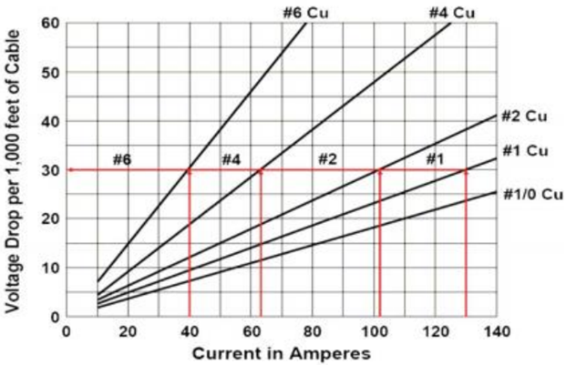
- Cable Voltage Drop:
The following graph shows an example of Cable Voltage drop plot to determine the voltage drop in cable. At the selected motor amperage and the given downhole temperature, the selection of a cable size that will give a voltage drop of less than 30 volts per 1000 feet is recommended. This curve will also enable you to determine the necessary surface voltage (motor voltage plus voltage drop in cable) required to operate the motor.
- Available space between tubing collars and casing:
Refer to the manufacturer’s cable catalog to determine if the size selected can be used within the proposed tubing and casing sizes. Cable diameter plus tubing-collar diameter will need to be less than the inside diameter of the casing.
NB: if power cost is a major concern, kilowatt-hour losses are calculated to justify the cable selection. An increase of the conductor size involves increased capital costs but decreased operating costs. So that, considering the initial cost of the cable and its associated KWh losses, the cable with the least value of total operating costs (Cable CAPEX plus OPEX over the expected life of the cable) has to be selected.
Cable Type:
Selection of the cable type is primarily based on fluids conditions, bottom-hole temperature and space limitation within the casing annulus. ESP cable is mainly compounded by a cable conductor, insulation, jacket, braid & covering and armor. Types, selection criteria, advantages and limitations of cable compounds were detailed in previous articles. Refer to the following links for more details:
Where there is not sufficient space to run round cable, use electric cable of flat configuration. The flat cable configuration induces a voltage imbalance. If it is significant, a transition splice may be required. Verify this with the manufacturer.
Cable Length:
The total cable length should be about 100 ft (30 m) longer than the measured pump setting depth in order to make surface connections a safe distance from the wellhead. Check the voltage available at the motor terminal block to avoid the possibility of low voltage starts. The available motor terminal voltage is the surface supply voltage minus the cable voltage drop in cable.
Cable Venting:
In gassy wells, it is necessary to vent gases from the cable prior to the motor controller to avoid explosive conditions. A cable venting box is available to protect the motor controller from such gases.
