ESP Power Cable Accessories

ESP Power Cable Accessories, namely: Cable Bands and Cable Guards, are used to protect and support ESP cable, control lines and injection lines. There are used also to protect the power cable from damage during installation, operation and pulling. In this article, the roles and specifications of these accessory equipment’s are detailed, as well as recommended practices related to their use and selection.

Cable Bands:

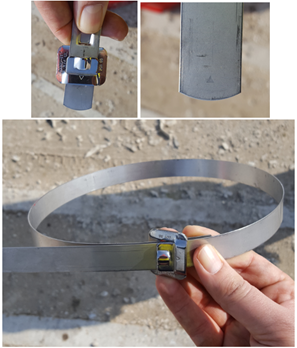
Cable bands are used to attach the cable to the tubing during installation. Bands are provided using three different materials. Black Steel Bands are used in wells with corrosive problems. Stainless Steel Bands are used in moderately corrosive well (with no H2S present in the well). And Monel Bands are used in corrosive environments.

Most cable bands are 3/4 in. (19 mm) wide and approximately .025 in. (0.6 mm) thick.

Cable bands can be installed by using hand-banding tools or by using power-banding tools. The advantage of power banding tools is the bands are attached with the same tension.

The following video shows how to install Cable bands using Power-Banding Tool:

Recommended practices related to cable bands and their use:

Continue reading

ESP design – Step 7: Electric Cables

The AC current is carried from the surface to the motor using either copper or aluminum cable conductors. For ESP applications, four sizes of conductors have been standardized: #1, #2, #4 and #6 AWG (AWG stands for “American Wire Gauge”). Electric Cables are available in either flat or round configurations.

An electric submersible cable is mainly compounded by a cable conductor, insulation, jacket, braid & covering and armor. These cable compounds are for protection against corrosive fluids and severe environments.

Cable selection involves the determination of Cable Size, Type and Length.

Cable Size:

The proper cable size is dependent on combined factors of voltage drop, amperage and available space between tubing collars and casing.

  • Cable Voltage Drop:

The following graph shows an example of Cable Voltage drop plot to determine the voltage drop in cable. At the selected motor amperage and the given downhole temperature, the selection of a cable size that will give a voltage drop of less than 30 volts per 1000 feet is recommended. This curve will also enable you to determine the necessary surface voltage (motor voltage plus voltage drop in cable) required to operate the motor.

Continue reading

ESP design – Step 5: Pump Type

In order to select the most suitable pump, Refer to the pump selection data table in the manufacturer’s catalog for pump type, range and pump performance curve. Based on expected fluid production rate and casing size, select the pump type which will be operating within the recommended operating range and nearest to the pump’s peak efficiency.

When two or more pump types have similar efficiencies at the desired production rate, the following recommendations should be considered to select the most adaptable pump to the well conditions:

The shape of the pump performance curve:

The  ability  of  a  pump to  adapt to  changes in  well  performance  depends  on  the characteristic  shape of  the pump performance  curve. A pump with a steep characteristic (i.e.  large  change  in  head with  respect  to  flow  rate)  is  less  suited  to  a well with  poorly defined  inflow  performance  (IPR),  especially  if  it  is  intended  to  produce  with  a  fixed drawdown.  For  such pumps,  a  small  loss  in  IPR  translates  to  a  large  fall  in pump  intake pressure and may result in gas locking. Conversely, the head produced by a pump with a flatter characteristic will change less for a given  change  of  flow  rate  and  can  therefore  be  used  over  a wider  variety  of  IPR’s with limited changes in intake pressure.

Refer to the article “Pump Performance Curves – part 02” for more details.

Continue reading

Variable Frequency Drive Basics

In this article, Variable Frequency Drive (also, named: Variable Speed Drive) basics are presented in a simple and easy way with explanation graphs. To understand how the Frequency Speed Controller operates, it is necessary to understand how the VSD supplies variable voltage and frequency for speed control.

The below block diagram illustration depicts a typical three-phase AC variable speed drive system. It has three main components: an Operator Control, a Drive Controller, and an AC Motor.

An Operator Control device provides a means to start and stop the motor and adjust the operating speed. The Drive Controller consists of a variety of components that work together to convert an AC input into a frequency and voltage output necessary to change the speed of an AC motor.

Main sections of a Variable Frequency Drive:

The converter section:

This section converts the incoming 3-phase AC voltage to DC voltage. The converter is essentially a 3-phase, full wave rectifier with Silicon Control Rectifiers, a specialized type of control diode, in the bridge.

The following video explains what SCR is and how it works:

Continue reading

Cable Armor

As per API RP11S5, cable armor is the outer covering of the cable which provides mechanical protection during installation and removal of cables. In addition to mechanical protection, the armor provides mechanical constraint against swelling and expansion of underlying elastomeric materials in case of any exposure to well fluids.

Continue reading