Power losses in cables

Cable power losses or power drop are due to the conductor resistance heating that occurs when current flows. These cable losses are more often called KW losses or I²R losses. This is expressed by the following formula:

Power losses = 3 × (I²R) /1000

Where: Power losses in kW units, I is the current (in amps) and R (in ohms) is the average conductor resistance.

How to lower the resistance in the cable?

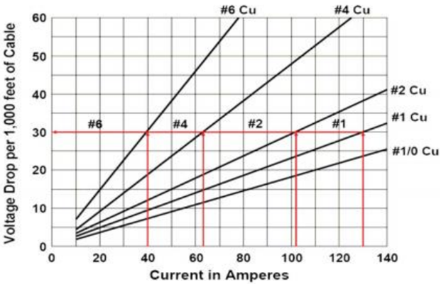
Power lost in a cable depends on the cable length, cable size and the current through the cable. Therefore, there are three ways to lower the resistance in the cable:

  • Shorten the length of the cable,
  • Increase the size of the conductor,
  • Decrease the current through the cable.

Continue reading

Step 8 – Downhole and Surface Accessory Equipment

This article “Downhole and Surface Accessory Equipment” is the step 8 of the nine-step procedure to design an ESP with an efficient and cost-effective performance. The required downhole and surface accessory equipment are discussed and recommended practices are highlighted.

Downhole Accessory Equipment:

  • Motor Lead Extension (MLE):

API RP 11S4 defines the Motor Lead Extension as a “special power cable extending from the pothead on the motor to above the end of the pump where it connects with the power cable. A low-profile cable (flat configuration) is usually needed in this area due to limited clearance between the pump housing and the well casing”. It is recommended to select a length at least 6 ft. (1.8 m) longer than the upper end of the pump. The length of MLE has to be select in a way to avoid a splice over a tubing collar. Doing so could allow the cable to catch on the wellbore casing and damage the equipment.

  • Banding Cable Protectors:

Cable protectors are used to protect the Motor Lead Cables from damage during installation, operation and pulling. The figures below show an example of cable protectors.

Continue reading

ESP design – Step 7: Electric Cables

The AC current is carried from the surface to the motor using either copper or aluminum cable conductors. For ESP applications, four sizes of conductors have been standardized: #1, #2, #4 and #6 AWG (AWG stands for “American Wire Gauge”). Electric Cables are available in either flat or round configurations.

An electric submersible cable is mainly compounded by a cable conductor, insulation, jacket, braid & covering and armor. These cable compounds are for protection against corrosive fluids and severe environments.

Cable selection involves the determination of Cable Size, Type and Length.

Cable Size:

The proper cable size is dependent on combined factors of voltage drop, amperage and available space between tubing collars and casing.

  • Cable Voltage Drop:

The following graph shows an example of Cable Voltage drop plot to determine the voltage drop in cable. At the selected motor amperage and the given downhole temperature, the selection of a cable size that will give a voltage drop of less than 30 volts per 1000 feet is recommended. This curve will also enable you to determine the necessary surface voltage (motor voltage plus voltage drop in cable) required to operate the motor.

Continue reading