ESP – Four Basic Design Types

Electrical submersible pumps could be installed in four different production environments where the criteria for the design changes as fluid properties and well conditions change. In this article, four basic design types of ESP’s will be presented.

The basic designs will change accordingly and will mainly depend on:

Continue reading

Effect of CO2 on downhole flowrate calculation

Downhole flow rate can be calculated from surface flow rate (stock tank barrels) using the following equation. It is assumed that no gas is dissolved in the water phase and the water formation volume factor is equal to one.

Downhole flow rate = [(Oil rate)sc × Bo] + [(Free GOR) × (Oil rate)sc × Gas FVF] + (Water rate)sc

Free GOR = Producing GOR – Solution GOR, therefore:

q = ( Qo × Bo ) + [ ( R – Rs) × Qo × Bg × 1000] + Qw

Where:

  • q = downhole flow rate (bbl/d or m3/d)
  • Qo = Oil flow rate at standard conditions (stb/d or m3sc/d)
  • Bo = Oil formation volume factor (bbl/stb or m3sc/m3sc)
  • R = Producing gas-oil ratio (scf/stb or m3sc/m3sc)
  • Rs = Solution gas-oil ration (scf/stb or m3sc/m3sc)
  • Bg = Gas formation vol. factor (bbl/mscf or m3sc/m3sc)
  • Qw = Water flow rate at standard conditions (stb/d or m3sc/d)

Effect of CO2 on downhole flowrate calculation:

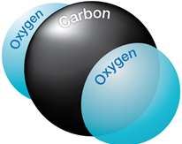
If CO2 is present, the calculation of downhole flow rate becomes more complex for many reasons:

Continue reading

Affinity Laws

The affinity laws, also known as “Pump Laws”, for pumps are used to express the relationship between variables involved in pump performance (such as head, flow rate, shaft speed) and power.

According to the affinity laws, the following relationships exist between the actual speed of the centrifugal pump and its most important performance parameters:

  • The flow rate of a pump changes directly proportional to its operating speed.
  • The head developed by the pump changes proportionally to the square of the speed.
  • The brake horsepower required to drive the pump changes proportionally to the cube of the speed.
  • The efficiency of the pump does not change with speed changes.

Continue reading

Total Dynamic Head Calculation

In this article “ Total Dynamic Head Calculation ”, the concept of the dynamic head is further detailed. As discussed in the previous article titled: “Total Dynamic Head (TDH)”, TDH is the sum of three basic components:

  1. Net Vertical Lift (NL) = is the net distance where the fluid must be lifted,
  2. Tubing Friction Loss (TFL) = Flow disturbance in the tubing string during pumping process,
  3. Tubing Head Pressure (THP) = Pressure which the unit must pump against (back pressure caused by choking on well head).

Continue reading

Total Dynamic Head (TDH)

To properly select the pump, well performance must be estimated. Fundamentally, well performance estimates define what additional energy (i.e., volumetric flow rate and differential pressure or head) must be supplied by the pump to deliver a desired stock tank flow rate (API RP11 S4).

It is common to simplify the procedure by combining or summarizing the additional energy that the pump must supply into a single term, Total Dynamic Head (TDH). TDH is a summation of the net vertical distance fluid must be lifted from an operating fluid level in the well, the frictional pressure drop in the tubing and the desired wellhead pressure.

TDH = HD + HF + HT

Continue reading