


Electrical submersible pumps could be installed in four different production environments where the criteria for the design changes as fluid properties and well conditions change. In this article, four basic design types of ESP’s will be presented.
The basic designs will change accordingly and will mainly depend on:
- High or low water cut
- High or low Gas Oil Ratios
- Light or heavy oil (viscous fluids?)
- Uncertain well productivity
The ESP basic designs could be classified into 4 main categories.
| Category | Reservoir conditions | Design Type |
| 1 | Low GOR / High Water Cut | High WOR Design |
| 2 | Significant amounts of gas | High GLR Design |
| 3 | Heavy oil | Viscous Fluid Design |
| 4 | Variable or uncertain production rate | Variable Speed Design |
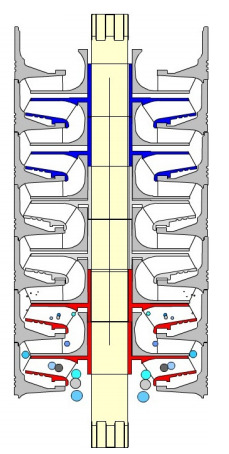
The presence of gas at the pump intake:
If gas is present in the produced fluid, a gas separator / gas handler may be required to achieve efficient operations. Refer to the article “ESP: Intake & Gas Separator” to review the different technologies of gas separator, as well as the article “ESP: Gas handling device” to review the additional benefits of gas handlers. The calculation of the percentage of free gas present at the pump intake was detailed in Step 3 of the 9 Step Design Procedure.
- High GOR ESP Experience and Development Concept for a Challenging Oil Field in the Sultanate of Oman
- High GOR Environment Gas Handling Solutions – Novomet
Viscous fluid / Emulsion / Sand production…:
If the produced fluid is quite viscous and/or trends to emulsify, the reservoir trends to produce sand, or any other extraordinary circumstances, some corrections to the pump design may be necessary to ensure a more efficient operation. In such case, contact the manufacturer for recommendations.
ESP Design Flow:
The submersible pumping system should be treated as a complete system, not a number of different components. The design should flow as follows:
1. Collect data and determine design goals.
2. Determine production rate based upon well productivity and design criteria.
3. Select tubing based upon well geometry, production rate, produced fluid composition, corrosion resistance requirements and design goals.
4. Select intake configuration based upon well geometry, produced fluid volumes, gas/solids separation requirements, produced fluid composition, abrasion / corrosion resistance requirements and design goals.
5. Select pump based upon well geometry, well temperature, pumped fluid volumes, pumped gas fraction, pumped fluid viscosity, produced fluid composition, abrasion / corrosion resistance requirements and design goals.
6. Select motor based upon well geometry, pump/intake/seal power requirements, production rate, produced gas & water fractions, input power quality, produced fluid composition, corrosion resistance requirements and design goals.
7. Select seal section based upon well geometry, power transmission requirements, thrust support requirements, well inclination, produced fluid properties, motor & seal oil capacity, motor operating temperature, well chemical treating program, corrosion resistance requirements and design goals.
8. Select cable based upon wellbore geometry, motor electrical requirements, produced fluid composition, well chemical treating program, corrosion resistance requirements and design goals.
9. Select wellhead based upon the casing / tubing / cable size, anticipated wellhead temperature and pressure, environmental / regulatory constraints, corrosion resistance requirements, and design goals.
10. Select switchboard / VSD based upon surface power requirements, well control requirements, soft-start requirements, surface environmental conditions, and design goals.
11. Select transformers based upon surface power requirements, motor starter type, surface environmental conditions, and design goals.
