


In this article, Variable Frequency Drive (also, named: Variable Speed Drive) basics are presented in a simple and easy way with explanation graphs. To understand how the Frequency Speed Controller operates, it is necessary to understand how the VSD supplies variable voltage and frequency for speed control.
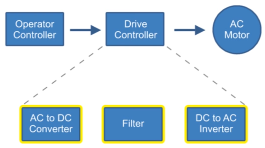
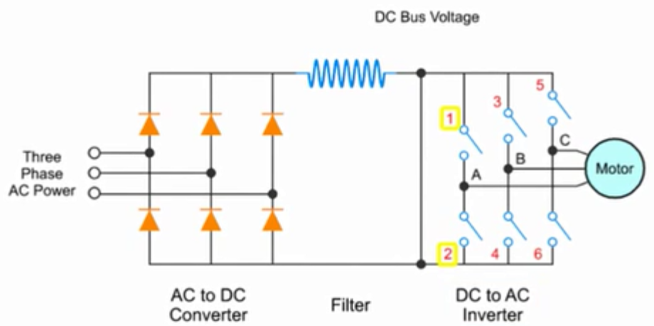
The below block diagram illustration depicts a typical three-phase AC variable speed drive system. It has three main components: an Operator Control, a Drive Controller, and an AC Motor.
An Operator Control device provides a means to start and stop the motor and adjust the operating speed. The Drive Controller consists of a variety of components that work together to convert an AC input into a frequency and voltage output necessary to change the speed of an AC motor.
Main sections of a Variable Frequency Drive:
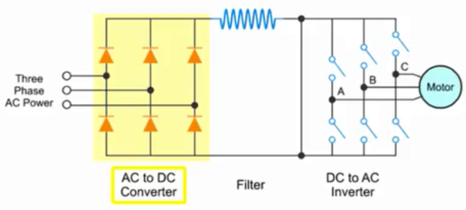
The converter section:
This section converts the incoming 3-phase AC voltage to DC voltage. The converter is essentially a 3-phase, full wave rectifier with Silicon Control Rectifiers, a specialized type of control diode, in the bridge.
The following video explains what SCR is and how it works:
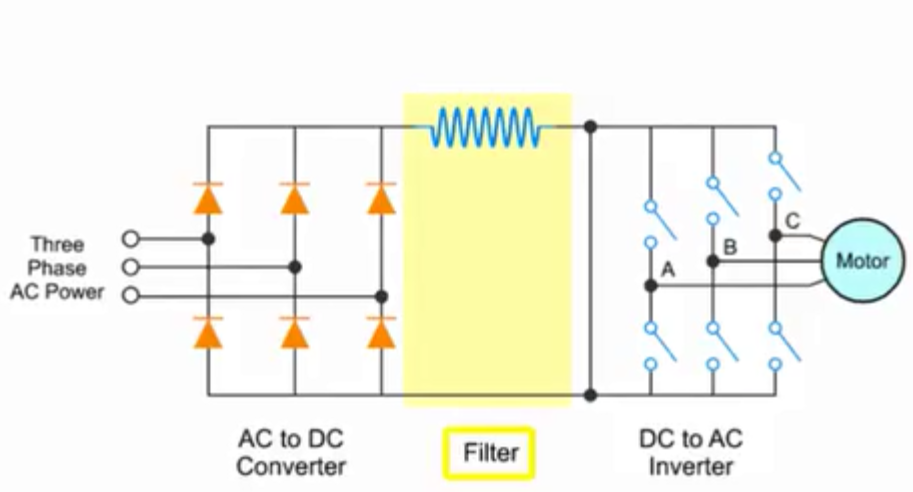
The filter section:
The incoming 3-phase has now been converted to DC. A large L-C filter then smooths the DC voltage. This is a series inductor used in conjunction with parallel capacitors. This inductor inhibits current surges while the capacitors inhibit voltage surges.
 The inverter section:
The final part of the Variable Frequency Drive consists of three inverter sections for converting the DC voltage back to AC voltage.
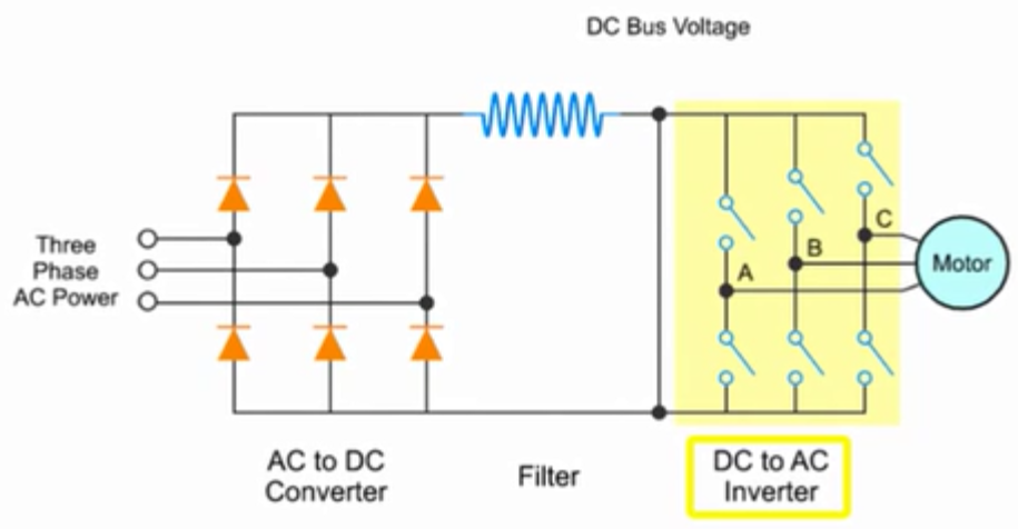
Each inverter section represents an output phase that contains two IGBT transistors. The IGBT transistors are connected in series across the DC bus. The output phase is derived from the center point between these two IGBT transistors (point A, B, and C in the previous graph). We can control when the IGBT transistors are turned on by applying a signal to its gate. We simply turn on and off the IGBT transistors at the appropriate time to apply plus or minus voltage to the phase approximating a sine wave. We now have frequency control by controlling the rate at which we turn on and off the IGBT transistors. In each pair of IGBT transistors, one IGBT generates the up component of the sine wave and the other one generates the down component.

The control circuits of the Variable Frequency Drive must be able to respond very quickly. At an output frequency of 80 HZ, an output IGBT transistors must turn on and off approximately every two-thousandths of a second (two milliseconds). The system is controlled by a microprocessor capable of executing an instruction every two microseconds (two-millionths of a second). To affect this control, the computer monitors all three input and output current phases, the DC bus, and all operator inputs.
The inverter output is not a true sine wave but an approximation based on the application of Pulse Width Modulation or PWM.
The longer a switch is on, the higher the AC output voltage. Conversely, the longer a switch is off, the lower the output voltage. This duration of on time for each pulse is called Pulse Width.
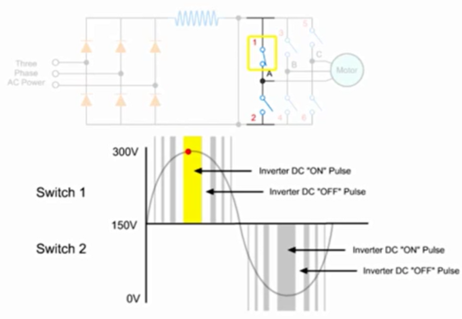
The time duration and intervals of these DC voltage pulses determine the synthesized AC output voltage and frequency.
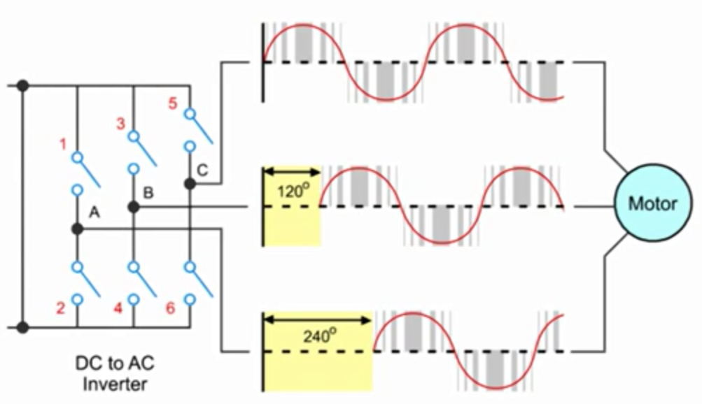
In a three-phase driver, the sine waves produced by each pair of inverter IGBTs are 120 degrees out of phase to ensure efficient operation of the motor.
Nota bene:
NB: For a more comprehensive description of the Variable Frequency Drive as utilized with electric submersible pumping, refer to the following SPE papers:
- SPE-8241-MS: “A Variable Speed Submersible Pumping System“,
- SPE-9215-MS: “Automatic Pump-Off Control For The Variable Speed Submergible Pump“.
NB: Refer to the following video for more details:
You May Also Like…

I’d like to start off by saying that I’m not the sharpest tool in the shed and I’m confused about one thing, the purpose of DC in the whole picture. AC gets converted to DC and then back to DC before going to the motor. But why convert to DC and then back? That’s the part I am having a hard time getting. Help me out. Thanks!