


The submersible pump system consists of both downhole and surface components. The main surface components are transformers, motor controllers, junction box and wellhead. The main downhole components are the motor, seal, pump and cable. Additional downhole components may be included to the system: data acquisition instrumentation, motor lead extension, cable bands and protectors, gas separator, check and drain valves.
The following video gives a quick equipment overview of the ESP submersible pumping system:
The following figure shows schematic diagram of a submersible pump installation:
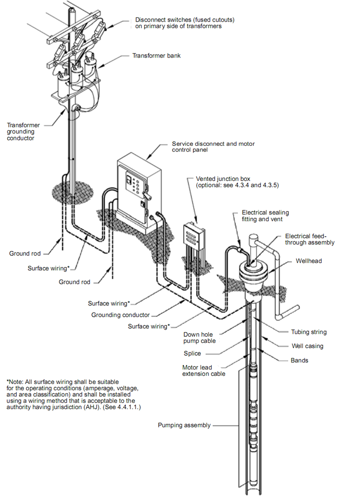
Components of an Electrical Submersible Pumping System (source: API RP 11S3)
The Pump discharge head:
The pump discharge head is usually a separate component that bolts onto the top of the pump section. Occasionally, the pump is built in either an upper tandem or single configuration. In these cases, the discharge head as an integral part of the pump assembly.
The Pump:
The pump is a multi-stage centrifugal pump and is generally built as center tandem configuration. The pump may be a single piece of pump or it may be made of two or more pumps bolted together.
The Pump Intake:
Fluid enters the pump through the pump intake. Usually, the pump intake is a separate component that bolts onto the bottom of the pump section. Occasionally, the pump is built in either a lower tandem or single configuration. In these cases, the pump intake as an integral part of the pump assembly.
A bolt-on intake is usually a standard screened intake but sometimes a gas separator is used instead.
The Seal:
The seal section is located between the pump intake and the motor. It is also named: motor protector or equalizer. the main functions of the seal are detailed in the post titled ” Motor Protectors “. The seal section can be a single unit or may be run in tandem where it is desired to additional seals and oil volume capabilities for high horsepower motor or more protection.
The Motor:
The motor is connected to the bottom of the seal. ESP motor is a two-pole, three-phase, squirrel cage induction design filled with high dielectric strength oil. A two-pole design means that it runs at 3600 rpm synchronous speed at 60-Hz power or roughly between 3400 to 3500 rpm actual operating speed, depending on the load. It operates on three-phase power at voltages as low as 230 and as high as 5000, with amperages between 12 and 200.
The motor may be a single motor or it may be made up of two or more motors bolted together in tandem.
Motor Base/data acquisition instrument:
The bottom of the motor may have an integral base (a bolt on base) or a downhole sensing device attached.
Electrical Power Cable:
Power is supplied to the electric motor by an electrical power cable. A special cable called a motor lead extension (MLE) or flat cable is installed from the motor terminals (or motor pothead) to above the end of the pump where it connects with the power cable. At this point, the main power cable is spliced to the MLC. The cable is banded to the pump and tubing up to the wellhead. The number of bands per joint of tubing depends on the size and type of cable and the well bore configuration.
Production Tubing:
The tubing conveys the produced fluid from the pump to the surface, into a flow-line. The type of tubing used will depend on well bore constrictions, fluid rates, and economics.
Wellhead:
The wellhead must have a provision for the electrical cable to pass through the hanger assembly to the surface. The tubing hanger holds a feed-through mandrel (also called: well penetrator) equipped with the proper seals to contain well pressure and prevent gas leaks at the surface. The power cables are connected to the two ends of this device via their three-phase connectors (also called: lower and upper pigtails).
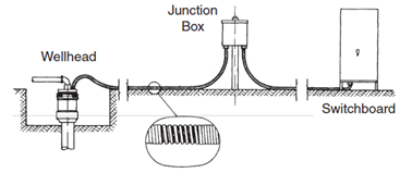
Junction Box:
The power cable coming from the well should be connected to a surface electric cable leading to the motor starter (switchboard or VSD). The two cables are joined in the junction box, also called “vent box”. This allows any gas that might have migrated up the cable to escape and vent to the atmosphere.
The remaining surface equipment consists of a motor controller and transformer(s). For more details, refer to the posts: Introduction to transformer: How it works? and Variable Frequency Drive Basics.
Submersible Pump System Selection and design considerations:
The submersible pumping system should be treated as an entire system, not a number of different components treated separately:
- The productivity and well fluid properties determine the size and type of pump.
- The fluid properties and wellbore configuration will determine the type of intake to be selected.
- The pump horsepower and wellbore configuration will determine what seals and motors should be selected.
- The production rate and wellbore configuration should be considered when selecting the tubing size and type.
- The motor electrical requirements, well bore configuration, chemical injection requirements, and fluid properties will determine the size and type of cable.
- The tubing, casing, and cable size along with the pressure and environmental constraints will determine what type of wellhead to use.
- The electrical and well control requirements will determine what motor starter and controller are needed.
- The electrical requirements and motor starter type, determine which transformers are needed.
You May Also Like…
- Centrifugal Pump ( ESP Pump)
- Pump Intake
- Motor Seal
- ESP Motor
- ESP Cable
- ESP Motor Switchboard
- Variable Frequency Drive Basics
- Introduction to transformer: How it works?
- Wellhead Equipment for ESP
- ESP Accessory Equipment
