Electrical submersible pumps could be installed in four different production environments where the criteria for the design changes as fluid properties and well conditions change. In this article, four basic design types of ESP’s will be presented.
The basic designs will change accordingly and will mainly
depend on:
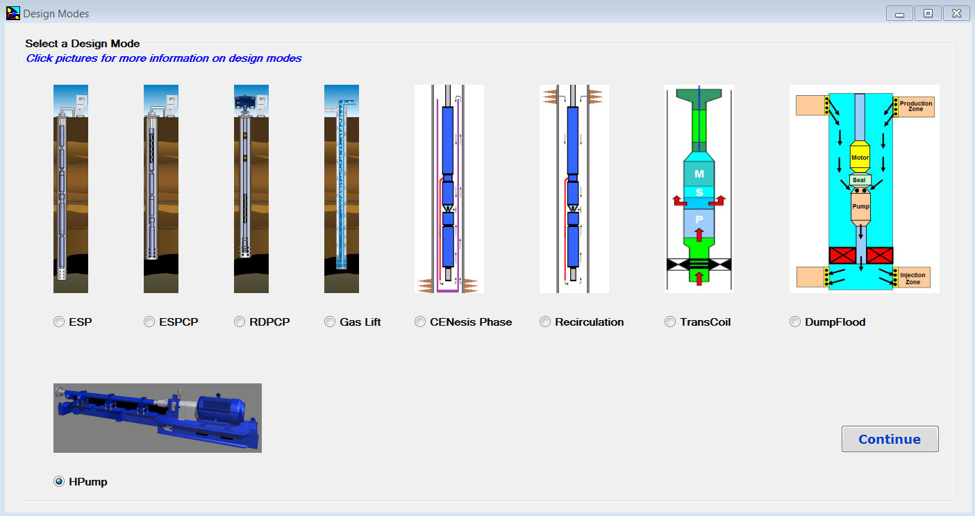
Baker Hughes Centrilift AutographPC ™ is an artificial lift and application simulation software. It’s a powerful tool to give a comprehensive and user-friendly system design. This software can be used to design production systems, including: electrical submersible pumping (ESP) systems; electrical submersible progressing cavity pumping (ESPCP™) systems; rod-driven progressing cavity pumping (RDPCP™) systems; horizontal surface pumping (HPump™) systems; and gas lift systems, etc.
Each system installation is unique and with this software, all the well information, including production characteristics, fluid properties and well conditions, can be entered during the initial design phase to produce the optimum solution for each sizing.
Once installed and launched, Design Modes Screen, shown in the following screenshot, appears. Design Modes screen has been added to AutographPC since July 12, 2017. This is the screen where the user can select a design mode and start a new sizing program.
Downhole flow rate can be calculated from surface flow rate (stock tank barrels) using the following equation. It is assumed that no gas is dissolved in the water phase and the water formation volume factor is equal to one.
This article walks through the suggested nine step procedure for selecting and designing an electric submersible pump. This nine step procedure for ESP design is a basic hand-design of simple water and light crude oil. For more complicated well conditions, such as high GOR, viscous oil, high-temperature wells, etc. a number of computer programs are available to automate this process.
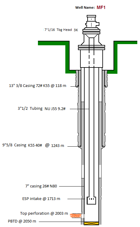
Step 1: Basic Data:
As detailed in the article “Step 1: Basic data ”, step 1 of the nine step design procedure is the most important step because all the others design steps will depend on the basic data selected in this step.
In this example, a high water cut well is considered. This is the simplest type of well for sizing submersible equipment.
The Y-tool is a solution to enable production-logging and well intervention below a working ESP at any point in time during production without pulling the completion string. The Y-tool is installed on the production tubing, providing two separate conduits. One conduit concentric with the production tubing and enables access to the reservoir below the ESP. The second conduit is offset and used to support the ESP system. Flow rates in different perforation intervals and other valuable geophysical information could be collected for production optimization and enhanced recovery plans.
With an ESP Y-tool in place, Operators are able to carry out wireline or coiled tubing logging, memory gauge deployment, tubing-conveyed perforation, well treatment and stimulation operations, effectively managing production operations and reservoir performance without pulling the ESP, dual ESP installation and bridge plug setting for water shutoff, etc.
Wireline or coiled tubing plugs can be used to seat in a nipple profile in the Y-tool to enable intervention or logging operation without retrieval of the completion. If required, the ESP can be run with these plugs in place to perform production logging or other well interventions.