


Gas lift operations and unloading procedure are described in the following demonstration video:
In order to further explain all these aspects and more simplify the process, gas lift operations have been described in the next paragraphs:
- Running the tubing / setting the packer:
The decision to complete the well implemented by setting and cementing the casing, is followed by running the tubing string.
An engineering prognosis is then completed. This specifies where the packer, side pocket mandrels and any other downhole production equipment are to be placed in the well. The side pocket mandrels are pre-loaded and hydro-tested, with dummy valves in the pockets. The packer is set somewhere above the perforations to the productive formation. As the tubing is correctly placed in the well, the packer is then set in accordance with the specifications in the engineering prognosis.
- Flanging Wellhead / Hydro-testing Casing / Tubing:
The packer is set with the designated weight and the master valve and wing valves are flanged up on the wellhead. After the wellhead is flanged, a hydro-test is performed by pumping into the annulus to achieve the specified pressure in the engineering prognosis.
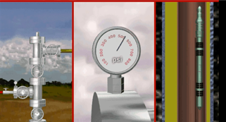
This pressure is held long enough to determine that no communication exists.
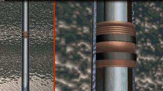
- Retrieving Dummy Valves:
After a successful hydro-test, the dummy valves are retrieved by wireline, starting with the bottom dummy valve and continuing, in sequence, retrieving the top one last.
As the kickover tool approaches the depth of the bottom mandrel, the operator will slow the speed and proceed through the mandrel. The operator will then start up hole slowly and the KOT kickover tool will make contact with the orienting sleeve located in the top portion of the mandrel.
This directs the kickover tool out over the dummy valve. The operator will then drop downward and allow the pulling tool to latch onto the latch and dummy valve, which can then be retrieved by jarring up. When the dummy valve is clear of the pocket, the operator will bring the valve to surface and remove it from the lubricator. This operation is repeated with each mandrel until all dummy valves have been retrieved.
Weatherford’s McMurry-Macco KOT kickover tool is unique from any other on the market because it does not have to be repined between runs, which saves considerably on wireline time and cost for the customer.
- Running Gas Lift Valves:
After all dummy valves have been retrieved; the wireline operator will remove the pulling tool from the bottom of the KOT kickover tool and simply attach a running tool. In running gas lift valves, the reverse order to the pulling procedure is implemented.
The operator begins with the top mandrel and installs each gas lift valve in sequence. The operator continues slowly through the mandrel, stops, and then starts up hole, kicking over the KOT tool, then jarring down until the gas lift valve is securely in the pocket and latched into place. This sheers a pin and leaves the valve in the pocket. The operator then proceeds back up the hole to repeat the process for each of the mandrels.
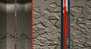
- Gas Lift Operation:
During the initial unloading process casing and tubing pressure gradients in the static loaded condition are equal.
All gas lift valves are in the open position from the weight of the hydrostatic fluid in the tubing and casing annulus.
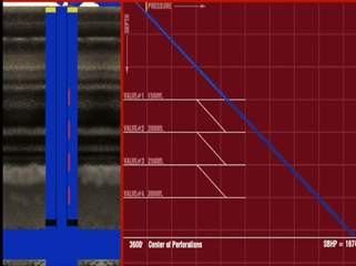
As gas is injected down the casing annulus it displaces the kill fluid through the opened gas lift valves into the tubing string and to the separator or storage tank.
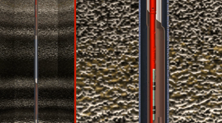
As the lift gas continues to displace and unload the fluid in the annulus, the pressure on the casing will continue to increase, maximizing the artificial lift capability.
When the annulus fluid is unloaded to the first valve depth the casing pressure will reached its designed kickoff pressure, in this case 800 psi.
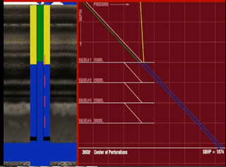
This pressure is sufficient to lower the casing fluid below the first mandrel and allow gas injection into the top valve. This injected gas causes a lighter gradient in the tubing allowing the well to unload the kill fluid entering the tubing string from the lower valves as the well continues to unload.
Once the annular fluid is displaced to the second valve depth, injection gas begins entering the tubing from the second valve. The combined injection of both the first and second valves exceeds the throughput of the surface input choke resulting in a casing pressure decline. This decline causes the top valve to close.
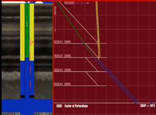
Injection continues from the second valve as the well continues to unload, lifting both the displaced kill fluid and produced well fluids. Note that as the well is unloaded to the second valve the pressure at the bottom of the tubing is less than the static bottomhole pressure of the reservoir. This differential known as, “Drawdown,” causes reservoir fluids to flow into the wellbore.
The same process is repeated every time the fluid in the casing is unloaded down below an additional valve, allowing the upper valve to close as the unloading process continues and the well is unloaded to it deepest point of injection.
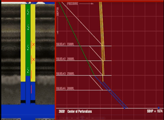
A pressure recorder installed at surface will record a casing pressure drop each time a valve closes. A reading of the recorded pressure as the well unloads will give an indication of the valve operating depth
In this case the well is unable to unload deeper because the flowing gradient pressure is higher than the available casing pressure. The diagram illustrates that this occurs at a depth of approximately 2900 ft, which is above the fourth valve depth. The bottom valve remains open but no gas is injected. Therefore, this well will lift from the third valve until condition change.
After the well is unloaded and stabilized, an accurate 24-hour test and a flowing survey can be run to evaluate and verify good operation. From the 24-hour well test and flowing bottomhole pressure, the well’s productivity index, (PI), can be determined.
Assuming the 24-hour test produced 500 BFPD, with the known static bottomhole pressure, of 1674 psi and a measured flowing bottomhole pressure of 1174 psi. The well’s PI can be calculated as: PI is equal to the produced fluid rate of 500 barrels per day divided by the static bottomhole pressure, 1674 psi, minus the flowing bottomhole pressure, 1174 psi.
Solving the equation the PI is calculated as 1 barrel per day per psi. This unit measure of the well’s productivity is used extensively in gas lift system design.
Reference:
Weatherford website: http://www.weatherford.com/en/products-services/production/artificial-lift-systems/gas-lift-systems
