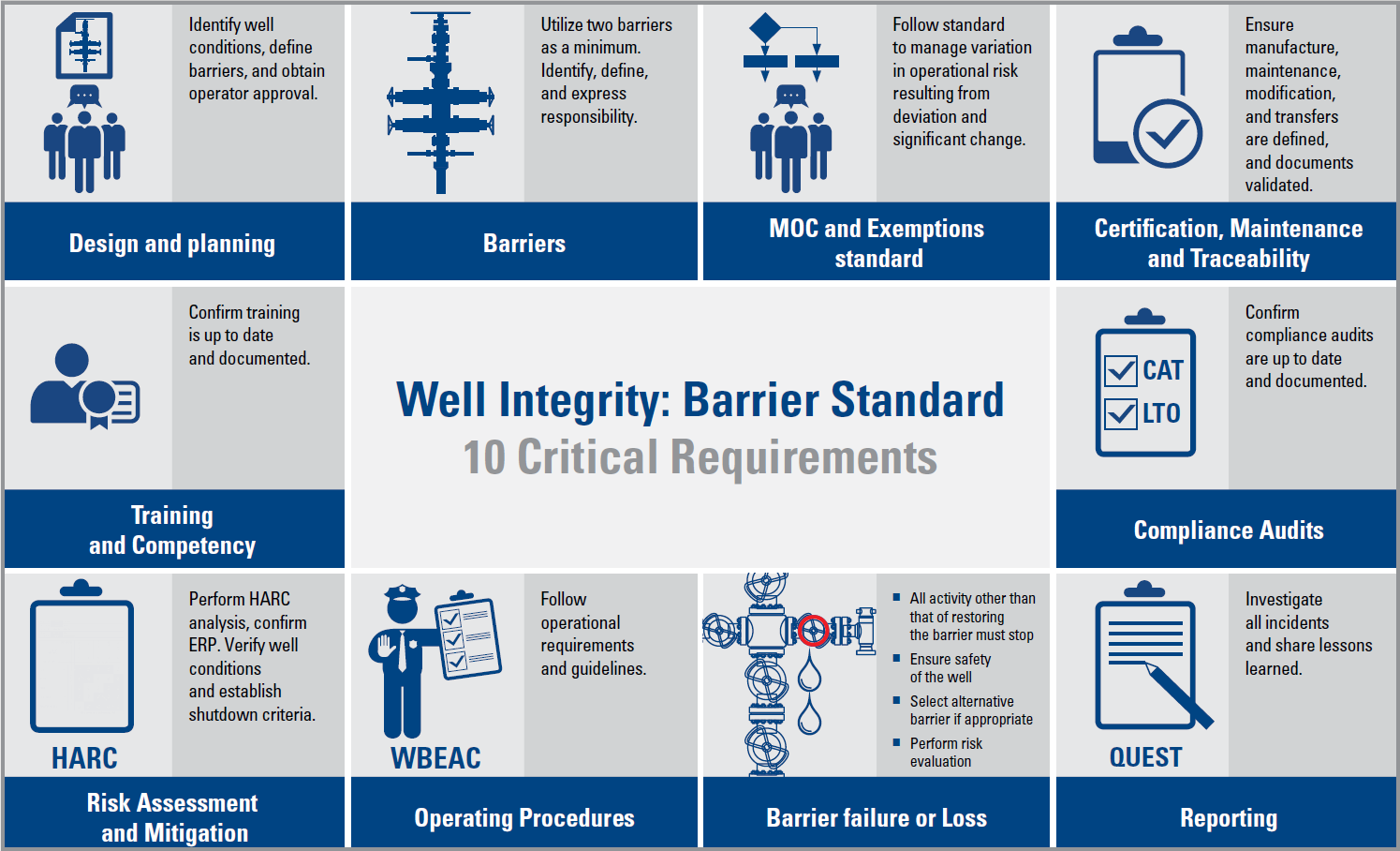
Major Reference Guides for Well Integrity

In this article, the major reference guides for Well Integrity are presented. These guides can be considered as reference documents as well as a basis for training classes on the subject of Well Integrity.

The standard defines the minimum functional and performance oriented requirements and guidelines for well design, planning and execution of safe well operations. The focal of the standard is well integrity.

Well integrity is defined to be “application of technical, operational and organizational solutions to reduce risk of uncontrolled release of formation fluids throughout the life cycle of a well”. The standard focuses on establishing well barriers by use of WBE’s (well barrier elements), their acceptance criteria, their use and monitoring of integrity during their life cycle. The standard also covers well integrity management and personnel competence requirements. The standard does not contain any well or rig equipment specifications.”

Continue reading

Introduction to Well Integrity

According to Norsok D-010, well integrity is defined as the “application of technical, operational and organizational solutions to reduce the risk of uncontrolled release of formation fluids and well fluids throughout the life cycle of a well”.

Well Integrity is defined in ISO/TS 16530-2 as: “containment and the prevention of the escape of fluids (i.e. liquids or gases) to subterranean formations or surface”

In API RP 65-2, well integrity is defined as: “a quality or condition of a well being structurally sound with competent pressure seals by application of technical, operational, and organizational solutions that reduce the risk of uncontrolled release of formation fluids throughout the well life cycle “.

Following from the aforementioned definitions of well integrity, the personnel planning the drilling and completion of wells will have to identify the solutions that give safe well life cycle designs that meet the minimum requirements of the standard.

Continue reading

5 things you should know about the ISO 16530-1 Well Integrity Standard

By Mark Plummer MSc BEng, Passionate Drilling Engineer – Oil & Gas | Geothermal | HPHT | Well Abandonment (P&A) | Well Examiner

In March, 2017 ISO released their Latest Well Integrity Standard, ISO 16530-1: Life Cycle Governance. In this article I will provide the background to the standard and discuss some of the key sections contained within.

BACKGROUND TO ISO 16530-1

1. It was developed by producing operating companies for oil and gas, and is intended for use in the petroleum and natural gas industry worldwide

2. It is intended to provide guidance to the Well Operator on managing well integrity throughout the well life cycle. Furthermore, it addresses the minimum compliance requirements for the well operator to claim conformity with ISO 16530-1.

3. It provides recommendations and techniques that well operators can apply in a scalable manner, based on a well’s specific risk characteristics

4. ISO 16530-1 is intended to compliment the 2014 issued ISO 16530-2 Technical Standard (TS) – Well Integrity for the Operational Phase, which is intended to provide the requirements to manage Well Integrity during the operation (production) phase only.

5. The standard is not applicable to:

  • Well control activities implemented to prevent or mitigate unintentional release of formation fluids from the well to its surroundings.
  • Wellbore integrity, sometimes referred to as “borehole stability”

KEY SECTIONS OF ISO 16530-1

Continue reading

What is Cement Bond Log (CBL)?

The Cement Bond Logging tools have become the standard method of evaluating cement jobs. They indicate how good the cement bond is. A cement bond log (CBL) documents an evaluation of the integrity of cement job performed on an oil well. It is basically a sonic tool which is run on wireline. Similar to a ringing bell, when no cement is bonded to the casing, pipe  is free to vibrate (loud sound). When the casing is bonded to hard cement, casing vibrations are attenuated proportionally to bonded surface.

CBL Measurement Principle:

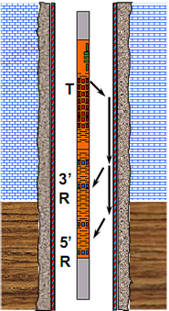
The basic tool configuration of CBL-VDL log is composed by One Transmitter and Two Receivers: the first Receiver is located 3 ft. from the Transmitter and is used for CBL Measurement. The second Receiver is located 5 ft. from the Transmitter and is used for Variable Density Log (VDL).

NB: CBL-VDL logging tools MUST be centralized.

The following video explains the basics of Cement Bond Log:

NB: API 10TR-1 is an API standard for Cement Sheath Evaluation.

Continue reading