The problem of heading (flow off and pump) is often encountered in gassy wells. This heading effect which can blow the tubing dry occurs as follows:
Gas expansion in the tubing as oil from the reservoir travels towards the surface (due to gas pressure decrease).
Formation of a gas “plunger” that can push the liquid above it out of the tubing and into the flow line at high speed. As the gas forces the liquids out of the tubing, the pressure in the tubing decreases rapidly and the gas expands even more.
This heading behavior of reservoir fluids causes cycles of high production followed by low or no production.
When heading process starts, the expanding gas pushes the liquid into the flowlines and increases production for a short time. In the meantime, the liquid leaving the tubing is replaced by more and more free gas. Eventually, the tubing is blown dry and production stops until the tubing fills with liquid again.
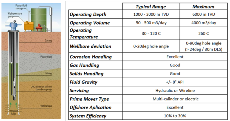
This article will present the typical ranges of jet pump operating parameters and discusses the advantages and disadvantages of jet pumps in oil wells applications.
The first consumer of water jets pump was James Thompson back in 1852. In 1870, J. M. Rankin introduced the theory of jet pump operation, afterward, a number of papers have been published to develop the technology. The work of Gasoline and O’Brien in 1933 is considered to be the standard reference work. It has been based on both theoretical and experimental results. Since that time, developments in the technology have continued to the point that today jet pumps have high operational flexibility.
What is Hydraulic Lift?
As a general description, Hydraulic Lift (Jet Pumps) represents pumping power fluid at high pressure and rate from surface to activate/drive a downhole pump. Power Fluid can be water or oil.
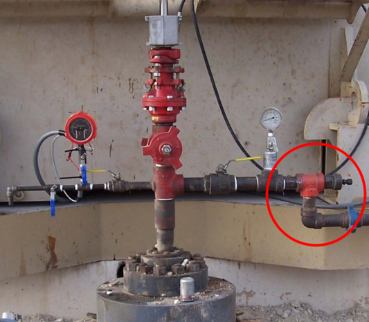
With Jet Pump applications the completion needs to have minimum 3 flowing conduits:
A conduit for power fluid injection (inside of the tubing in case of standard flow, and in the annular space in case of reverse flow).
For reservoir fluid flow (below the JP & packer).
And a conduit for commingled fluid flow to the surface.
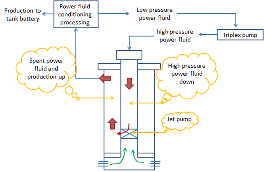
Jet Pump working principle:
The jet pump artificial lift system is composed of two principal parts: the surface pumping equipment and the downhole jet pump. In the surface, the reciprocating pump transfers energy to the fluid increases its pressure, drove through surface piping, production tubing (or annular space) until the jet pump, placed on the bottom.
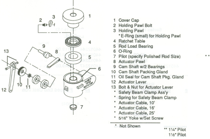
The constant up-and-down movement of a sucker rod creates excessive friction between rods and tubing which can result in premature rod and tubing failures due to excessive wear. If left unchecked, this generally requires a costly intervention to make repairs.
To extend the sucker rod run life, one of the widely used techniques is the use of rod rotators. A rod rotator is a mechanical device installed on the polished rod between the carrier and the polished rod clamp. It incrementally rotates the rod with each stroke. A rotating mechanism with an actuator lever arm is connected to the walking beam with a metal string. As the surface unit moves up and down, it pulls and releases this metal string so that, moves the actuator lever arm up and down. The rotation mechanism is activated and this slowly rotates the polished rod and the rod string below.