Rod Rotator extends the life of rod-pumped wells

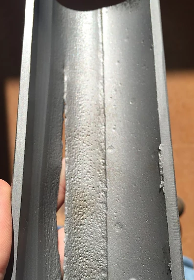
The constant up-and-down movement of a sucker rod creates excessive friction between rods and tubing which can result in premature rod and tubing failures due to excessive wear. If left unchecked, this generally requires a costly intervention to make repairs.

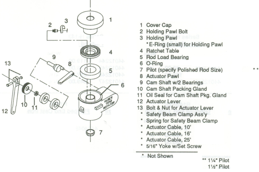
To extend the sucker rod run life, one of the widely used techniques is the use of rod rotators. A rod rotator is a mechanical device installed on the polished rod between the carrier and the polished rod clamp. It incrementally rotates the rod with each stroke. A rotating mechanism with an actuator lever arm is connected to the walking beam with a metal string. As the surface unit moves up and down, it pulls and releases this metal string so that, moves the actuator lever arm up and down. The rotation mechanism is activated and this slowly rotates the polished rod and the rod string below.

Continue reading

Tubing Rotator reduces rod pumping failures

The tubing, in a well produces by the mean of a rod pumping system, represents the second largest investment in the well. Every day, every stroke on the pumping unit can cause wear in the tubing. On ever stroke the rods move up and down. Especially for deviated wells, the rods will always tend to lie on the downside of the tubing. So, on every stroke of the pumping unit, the rods are wearing a path into the metal of the tubing, path that will become a hole in the tubing.

Rod-wear track in tubing (from a 1” Spray-Metal coupling rubbing in 2 7/8” tubing)

Tubing Wear:

In a typical pumping well running at 10 strokes per minute, the rods will move against the tubing 14400 times every day. This wear will eventually cause a tubing failure. A common tubing failure is termed a “tubing split” and normally will be thin on one side of the tubing’s internal surface (about 20% of the tubing’s circumference) and can be detected by pinging with a hammer, cutting open the tubing, or running a thumb inside the tubing to feel for the thin area. The outside of the tubing will normally have a “tubing split” where a thin crack 1 to 5 inches long runs along the longitudinal axis of the tubing as shown in the following figure.

Continue reading