ESP Design – Hand Calculations

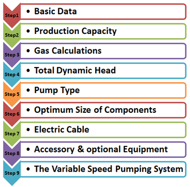
This article walks through the suggested nine step procedure for selecting and designing an electric submersible pump. This nine step procedure for ESP design is a basic hand-design of simple water and light crude oil. For more complicated well conditions, such as high GOR, viscous oil, high-temperature wells, etc. a number of computer programs are available to automate this process.

Step 1: Basic Data:

As detailed in the article “Step 1: Basic data ”, step 1 of the nine step design procedure is the most important step because all the others design steps will depend on the basic data selected in this step.

In this example, a high water cut well is considered. This is the simplest type of well for sizing submersible equipment.

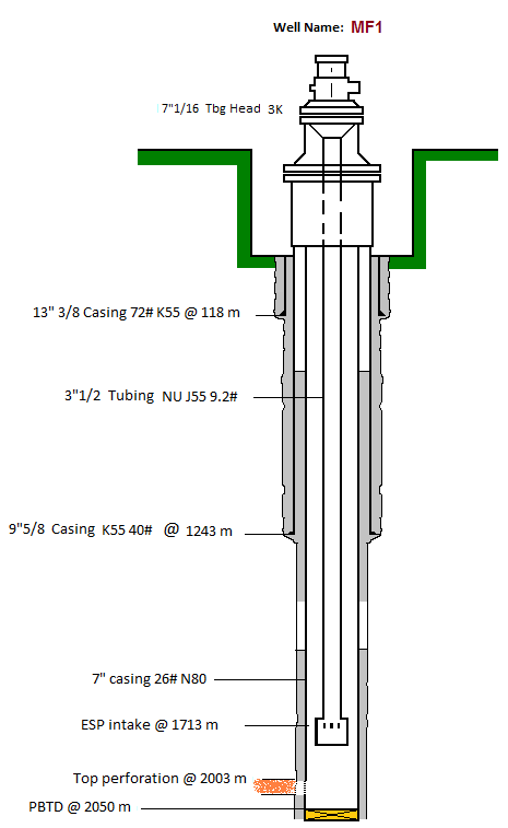
  • Well Profile:

Vertical Well

Casing: 7” 26#

Tubing: 3 ½” 9,2# N80 NU

Top perforation: 2003m

Pump Intake depth: 1713m

Continue reading

ESP Nine Step Design Procedure

Centrilift has established a nine-step procedure to design the appropriate electrical submersible pump in order to have an efficient and cost-effective performance. This article gives an overview of the ESP nine step design procedure and outlines the procedure as a manual process to illustrate the design steps. Each of the nine steps will be explained in detail in the next articles.

Specific examples will be worked through in each step of the ESP design.

This nine step procedure is a basic hand-design of simple water and light crude oil. For more complicated well conditions, such as high GOR, viscous oil, high-temperature wells, there are many of available ESP design software (e.g. Prosper software – Product of Petroleum Expert; Pipesim software – Product of Schlumberger; Autograph PC software – Product of Baker Hughes; Solution Sizing Software – Product of General Electric; DesignRite Software – Product of Schlumberger). The fashion of use of each of these ESP design software will be presented and explained in detail in upcoming articles in our website.