ESP Design – Hand Calculations

This article walks through the suggested nine step procedure for selecting and designing an electric submersible pump. This nine step procedure for ESP design is a basic hand-design of simple water and light crude oil. For more complicated well conditions, such as high GOR, viscous oil, high-temperature wells, etc. a number of computer programs are available to automate this process.

Step 1: Basic Data:

As detailed in the article “Step 1: Basic data ”, step 1 of the nine step design procedure is the most important step because all the others design steps will depend on the basic data selected in this step.

In this example, a high water cut well is considered. This is the simplest type of well for sizing submersible equipment.

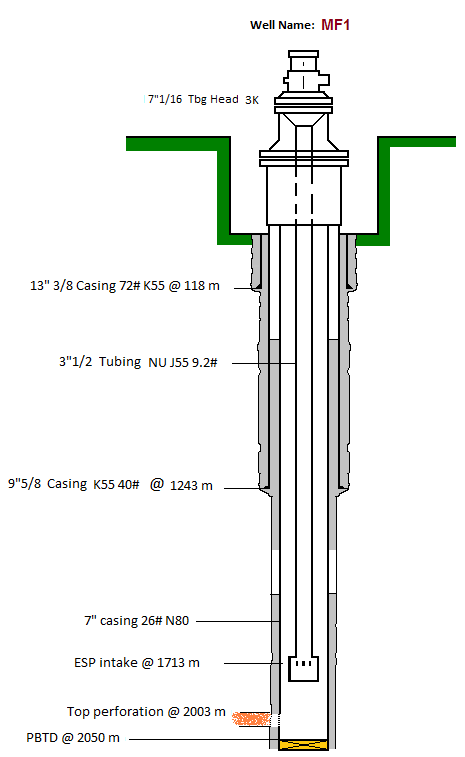
  • Well Profile:

Vertical Well

Casing: 7” 26#

Tubing: 3 ½” 9,2# N80 NU

Top perforation: 2003m

Pump Intake depth: 1713m

Continue reading

Step 8 – Downhole and Surface Accessory Equipment

This article “Downhole and Surface Accessory Equipment” is the step 8 of the nine-step procedure to design an ESP with an efficient and cost-effective performance. The required downhole and surface accessory equipment are discussed and recommended practices are highlighted.

Downhole Accessory Equipment:

  • Motor Lead Extension (MLE):

API RP 11S4 defines the Motor Lead Extension as a “special power cable extending from the pothead on the motor to above the end of the pump where it connects with the power cable. A low-profile cable (flat configuration) is usually needed in this area due to limited clearance between the pump housing and the well casing”. It is recommended to select a length at least 6 ft. (1.8 m) longer than the upper end of the pump. The length of MLE has to be select in a way to avoid a splice over a tubing collar. Doing so could allow the cable to catch on the wellbore casing and damage the equipment.

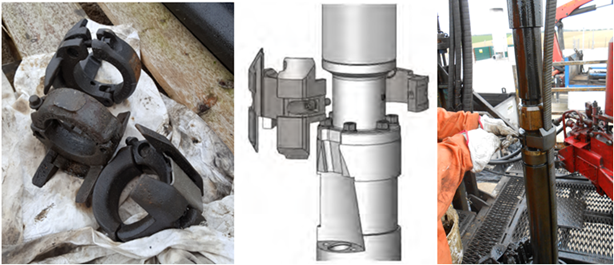
  • Banding Cable Protectors:

Cable protectors are used to protect the Motor Lead Cables from damage during installation, operation and pulling. The figures below show an example of cable protectors.

Continue reading

ESP design – Step 2: Production Capacity

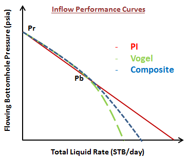
Once the first step “Collect basic data” is performed, we pass to the ” step 2: Production Capacity “ of the ESP Nine Step Design Procedure. It consists on predicting the well inflow performance which represents the relationship between pressure and flow rate at the well face of an individual well and it is physically defined as the well flowing bottom-hole pressure (Pwf) as a function of production rate. It describes the flow in the reservoir.

Many inflow performance relationships (IPR’s) are described in the literature. In this article, we will briefly present three of the most widely used IPR’s to describe the well performance:


Continue reading