Introduction to AutographPC Sizing and Simulation Software

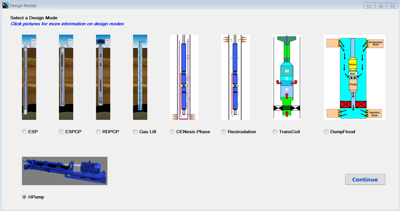
Baker Hughes Centrilift AutographPC ™ is an artificial lift and application simulation software. It’s a powerful tool to give a comprehensive and user-friendly system design. This software can be used to design production systems, including: electrical submersible pumping (ESP) systems; electrical submersible progressing cavity pumping (ESPCP™) systems; rod-driven progressing cavity pumping (RDPCP™) systems; horizontal surface pumping (HPump™) systems; and gas lift systems, etc.

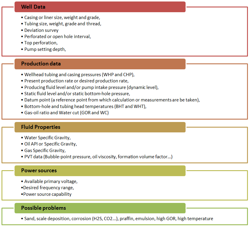
Each system installation is unique and with this software, all the well information, including production characteristics, fluid properties and well conditions, can be entered during the initial design phase to produce the optimum solution for each sizing.

Once installed and launched, Design Modes Screen, shown in the following screenshot, appears. Design Modes screen has been added to AutographPC since July 12, 2017. This is the screen where the user can select a design mode and start a new sizing program.


Continue reading

ESP design – Step 1: Basic data

As described in the previous article ESP nine step design procedure, Centrilift has established a nine-step procedure to design the appropriate electrical submersible pump. The first step of this ESP design procedure, and certainly the most important step, consists on collecting the basic data. This is the most important step because all the others design steps will depend on the basic data selected in step 1. If the basic data quality is good the design will be good and the ESP will operate at its optimum conditions. Otherwise, if the input data quality is poor the design will usually be marginal.

A list of required data is outlined next:

ESP Nine Step Design Procedure

Centrilift has established a nine-step procedure to design the appropriate electrical submersible pump in order to have an efficient and cost-effective performance. This article gives an overview of the ESP nine step design procedure and outlines the procedure as a manual process to illustrate the design steps. Each of the nine steps will be explained in detail in the next articles.

Specific examples will be worked through in each step of the ESP design.

This nine step procedure is a basic hand-design of simple water and light crude oil. For more complicated well conditions, such as high GOR, viscous oil, high-temperature wells, there are many of available ESP design software (e.g. Prosper software – Product of Petroleum Expert; Pipesim software – Product of Schlumberger; Autograph PC software – Product of Baker Hughes; Solution Sizing Software – Product of General Electric; DesignRite Software – Product of Schlumberger). The fashion of use of each of these ESP design software will be presented and explained in detail in upcoming articles in our website.

Variable Frequency Drive Basics

In this article, Variable Frequency Drive (also, named: Variable Speed Drive) basics are presented in a simple and easy way with explanation graphs. To understand how the Frequency Speed Controller operates, it is necessary to understand how the VSD supplies variable voltage and frequency for speed control.

The below block diagram illustration depicts a typical three-phase AC variable speed drive system. It has three main components: an Operator Control, a Drive Controller, and an AC Motor.

An Operator Control device provides a means to start and stop the motor and adjust the operating speed. The Drive Controller consists of a variety of components that work together to convert an AC input into a frequency and voltage output necessary to change the speed of an AC motor.

Main sections of a Variable Frequency Drive:

The converter section:

This section converts the incoming 3-phase AC voltage to DC voltage. The converter is essentially a 3-phase, full wave rectifier with Silicon Control Rectifiers, a specialized type of control diode, in the bridge.

The following video explains what SCR is and how it works:

Continue reading

Introduction to transformer: How it works?

The transformer is used to convert the incoming voltage at the location to the correct voltage (for the submersible motor in case of ESP). Transformer selection is based on mainly 4 parameters:

  • Power rating in KVA (Kilo Volt Amperes),
  • Primary voltage,
  • Secondary voltage,
  • Tap arrangement.

Power rating in KVA for three phase transformer:

The calculation of power rating in KVA for a Three Phase Transformer is based on Winding Voltage and Amperage information. The simple formula to calculate the rating of three phase transformers is:

KVA = (√3. V x I) /1000

Refer to the post titled “How to Calculate the Required KVA Rating for three Phase Transformers? ” for more details.

Continue reading