Electrical submersible pumps could be installed in four different production environments where the criteria for the design changes as fluid properties and well conditions change. In this article, four basic design types of ESP’s will be presented.
The basic designs will change accordingly and will mainly
depend on:
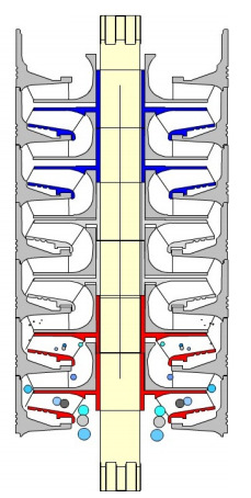
The Y-tool is a solution to enable production-logging and well intervention below a working ESP at any point in time during production without pulling the completion string. The Y-tool is installed on the production tubing, providing two separate conduits. One conduit concentric with the production tubing and enables access to the reservoir below the ESP. The second conduit is offset and used to support the ESP system. Flow rates in different perforation intervals and other valuable geophysical information could be collected for production optimization and enhanced recovery plans.
With an ESP Y-tool in place, Operators are able to carry out wireline or coiled tubing logging, memory gauge deployment, tubing-conveyed perforation, well treatment and stimulation operations, effectively managing production operations and reservoir performance without pulling the ESP, dual ESP installation and bridge plug setting for water shutoff, etc.
Wireline or coiled tubing plugs can be used to seat in a nipple profile in the Y-tool to enable intervention or logging operation without retrieval of the completion. If required, the ESP can be run with these plugs in place to perform production logging or other well interventions.
ESP Power Cable Accessories, namely: Cable Bands and Cable Guards, are used to protect and support ESP cable, control lines and injection lines. There are used also to protect the power cable from damage during installation, operation and pulling. In this article, the roles and specifications of these accessory equipment’s are detailed, as well as recommended practices related to their use and selection.
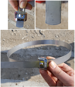
Cable Bands:
Cable bands are used to attach the cable to the tubing during installation. Bands are provided using three different materials. Black Steel Bands are used in wells with corrosive problems. Stainless Steel Bands are used in moderately corrosive well (with no H2S present in the well). And Monel Bands are used in corrosive environments.
Most cable bands are 3/4 in. (19 mm) wide and approximately .025 in. (0.6 mm) thick.
Cable bands can be installed by using hand-banding tools or by using power-banding tools. The advantage of power banding tools is the bands are attached with the same tension.
The following video shows how to install Cable bands using Power-Banding Tool:
Recommended practices related to cable bands and their use:
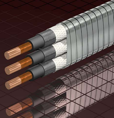
The Motor Lead Extension is a “special power cable extending from the pothead on the motor to above the end of the pump where it connects with the power cable (API RP 11S4).
A low-profile cable (flat configuration) is usually needed in this area due to limited clearance between the pump housing and the well casing”.
It is recommended to select a length at least 6 ft. (1.8 m) longer than the upper end of the pump. The length of MLE has to be select in a way to avoid a splice over a tubing collar. Doing so could allow the cable to catch on the wellbore casing and damage the equipment.
The motor lead extension operates under extremely adverse conditions. This is due to the restricted size, the high mechanical stresses, and the high temperatures involved. Because of these effects, motor lead extensions are usually replaced every time a cable is reused.
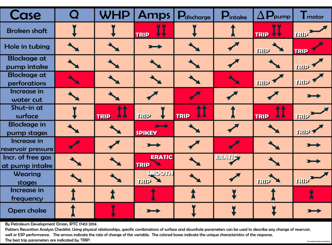
One of my clients brought this diagram to my attention recently. The paper, by Petroleum Development Oman and Engineering Insight Ltd of Aberdeen, was very useful and included an especially useful diagram, but the diagram was not so easy to read or print in a larger size. I tried to improve the image so that it would be even more helpful. All credit goes to the authors and their paper IPTC 17413 2014, available on SPE’s OnePetro.