ESP Motor Shroud: Applications, Configurations and Selection Criteria

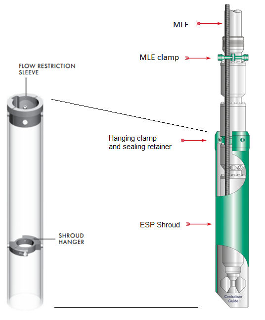
The ESP motor Shroud is a cylinder fitted around the Motor, Protector and Intake sections of an ESP. It is designed to provide cooling to the motor when fluid velocities are below minimum by reducing the annular area between the ESP and the casing bore.

The Shroud is simply constructed with a length of tube long enough to swallow the Motor, Protector and Intake sections, and is bolted with a split clamp unit to first ESP neck located above Intake. The MLE cable is run through the shroud. The shroud assembly is made up of a jacket (a length of casing or pipe), a hanging clamp and sealing retainer for the top, and a centralizer for the bottom.

Above the Shroud, an MLE Clamp is normally fitted to secure the MLE to the Discharge Head. At the bottom end, a Centralizer Guide is fitted to help secure the ESP section within the Shroud. The Shroud can be manufactured from a thin casing, stainless steel or fiberglass.

Continue reading

Step 9 – Variable Speed Submersible Pumping System

Compared to conventional ESP installations with constant motor speeds, installations running at variable frequencies have several advantages. The most important benefit of a Variable Speed Submersible Pumping System is the wide flexibility of the variable frequency ESP system that permits perfect matching of the lift capacity of the ESP system and the well’s productivity. Therefore, it operates over a much broader range of capacity, head, and efficiency.

NB: Variable Frequency Drive basics (also, named: Variable Speed Drive) are presented and discussed in the article “Variable Frequency Drive Basics”.

Since a submersible pump motor is an induction motor, its speed is proportional to the frequency of the electrical power supply. This relationship between variables involved in pump performance (such as head, flow rate, shaft speed) and power is known as “Affinity Laws” (also called “Pump Laws”).

Continue reading

ESP design – Step 7: Electric Cables

The AC current is carried from the surface to the motor using either copper or aluminum cable conductors. For ESP applications, four sizes of conductors have been standardized: #1, #2, #4 and #6 AWG (AWG stands for “American Wire Gauge”). Electric Cables are available in either flat or round configurations.

An electric submersible cable is mainly compounded by a cable conductor, insulation, jacket, braid & covering and armor. These cable compounds are for protection against corrosive fluids and severe environments.

Cable selection involves the determination of Cable Size, Type and Length.

Cable Size:

The proper cable size is dependent on combined factors of voltage drop, amperage and available space between tubing collars and casing.

  • Cable Voltage Drop:

The following graph shows an example of Cable Voltage drop plot to determine the voltage drop in cable. At the selected motor amperage and the given downhole temperature, the selection of a cable size that will give a voltage drop of less than 30 volts per 1000 feet is recommended. This curve will also enable you to determine the necessary surface voltage (motor voltage plus voltage drop in cable) required to operate the motor.

Continue reading

ESP design – Step 5: Pump Type

In order to select the most suitable pump, Refer to the pump selection data table in the manufacturer’s catalog for pump type, range and pump performance curve. Based on expected fluid production rate and casing size, select the pump type which will be operating within the recommended operating range and nearest to the pump’s peak efficiency.

When two or more pump types have similar efficiencies at the desired production rate, the following recommendations should be considered to select the most adaptable pump to the well conditions:

The shape of the pump performance curve:

The  ability  of  a  pump to  adapt to  changes in  well  performance  depends  on  the characteristic  shape of  the pump performance  curve. A pump with a steep characteristic (i.e.  large  change  in  head with  respect  to  flow  rate)  is  less  suited  to  a well with  poorly defined  inflow  performance  (IPR),  especially  if  it  is  intended  to  produce  with  a  fixed drawdown.  For  such pumps,  a  small  loss  in  IPR  translates  to  a  large  fall  in pump  intake pressure and may result in gas locking. Conversely, the head produced by a pump with a flatter characteristic will change less for a given  change  of  flow  rate  and  can  therefore  be  used  over  a wider  variety  of  IPR’s with limited changes in intake pressure.

Refer to the article “Pump Performance Curves – part 02” for more details.

Continue reading

ESP design – Step 4: Total Dynamic Head

The step4 of the ESP design consists on determining the total dynamic head required to pump the desired capacity. It is common to simplify the procedure by combining or summarizing the additional energy that the pump must supply into a single term, Total Dynamic Head (TDH). TDH is a summation of the net vertical distance fluid must be lifted from an operating fluid level in the well, the frictional pressure drop in the tubing and the desired wellhead pressure.

TDH = HD + HF + HT

  • TDH: total dynamic head in feet (meters) delivered by the pump when pumping the desired volume.
  • HD: vertical distance in feet (meters) between the wellhead and the estimated producing fluid level at the expected capacity.
  • HF: the head required to overcome friction loss in tubing measured in feet (meters).
  • HT: the head required to overcome friction loss in the surface pipe, valves, and fittings, and to overcome elevation changes between wellhead and tank battery.

PS: HT is normally measured in gauge pressure at the wellhead. It can be converted to head, in feet (meters) as follows: HT = (psi / (0.433 psi/ft x sp. gr.)

Continue reading