ESP design – Step 6: Optimum Size of Compounds

ESP compounds have different sizes and can be assembled in a variety of combinations. These combinations must be carefully determined to operate the ESP with production requirement, downhole conditions, material strength and temperature limits, etc. to select the optimum size of compounds.

Pump:

To determine the required number of stages of the pump to produce the anticipated capacity; just divide the Total Dynamic Head (TDH) by the Head developed by Stage.

Refer to the article “ESP design – Step 4: Total Dynamic Head” to review how the TDH is calculated.

The Head developed per stage is deducted from the published performance curve which shows the discharge head developed by the pump. It is an experimental curve given by the manufacturer and obtained with fresh water at 60 F under controlled conditions detailed in API R11 S2. Refer to the articles “Pump Performance Curves – part 01” and “Pump Performance Curves – part 02” for more details.

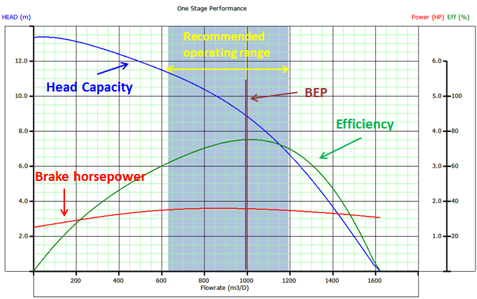
Once calculated, divide the TDH by the Head developed per stage to get the Total Number of Stages required to produce the anticipated capacity.

Total Stages = TDH / [(Head / stage)]

Continue reading

ESP design – Step 5: Pump Type

In order to select the most suitable pump, Refer to the pump selection data table in the manufacturer’s catalog for pump type, range and pump performance curve. Based on expected fluid production rate and casing size, select the pump type which will be operating within the recommended operating range and nearest to the pump’s peak efficiency.

When two or more pump types have similar efficiencies at the desired production rate, the following recommendations should be considered to select the most adaptable pump to the well conditions:

The shape of the pump performance curve:

The  ability  of  a  pump to  adapt to  changes in  well  performance  depends  on  the characteristic  shape of  the pump performance  curve. A pump with a steep characteristic (i.e.  large  change  in  head with  respect  to  flow  rate)  is  less  suited  to  a well with  poorly defined  inflow  performance  (IPR),  especially  if  it  is  intended  to  produce  with  a  fixed drawdown.  For  such pumps,  a  small  loss  in  IPR  translates  to  a  large  fall  in pump  intake pressure and may result in gas locking. Conversely, the head produced by a pump with a flatter characteristic will change less for a given  change  of  flow  rate  and  can  therefore  be  used  over  a wider  variety  of  IPR’s with limited changes in intake pressure.

Refer to the article “Pump Performance Curves – part 02” for more details.

Continue reading

Motor Seal

The Motor seal is installed below the intake and above the electric motor. It is also named: Equalizer, balance chamber, or Protector. Seal section types, functions, components, and applications are detailed in this article.

In addition to the main function of transferring the motor torque to the pump shaft, the seal section performs four primary functions (Equalization, Expansion, Isolation, & “Aabsorbsion):

  • Equalizes the pressure in the wellbore with the pressure inside the motor,
  • Provides area for motor oil expansion volume (induced by temperature changes in the motor),
  • Isolates the well fluid from the clean motor oil,
  • Absorbs the pump shaft thrust load (it houses the thrust bearing that carries the axial thrust developed by the pump, it can either be upthrust or downthrust, depending on the pumping conditions – obviously, for fixed impeller type only).


PS: The motor, pump and seal are often submerged below several thousand feet of fluid. The seal section allows the pressure in the motor and the annulus to equalize, so that there is very little pressure across the shaft seals or the pothead connection.

PS: When selecting the protector, we need to be certain that the protector shaft is capable of delivering the full torque required without exceeding its yield strength which could result in a broken shaft.

Continue reading

ESP: Gas handling device

Gas  handling  devices  may  be  a  better  alternative  for  wells  prone  to  high  free  gas, slugging, foams and emulsions. These are essentially centrifugal pumps with large stages, mixed  (or  axial)  impellers,  large  vane  openings,  steep  vane  exit  angles  and  sometimes include multiple  vanes. 

Instead of separating, their purpose is to break large gas bubble into smaller ones thereby reducing the risk of gas locking and making it easier for gas to be re-absorbed into solution, and to homogenize the gas with liquid phases, prior to entering the pump intake.

An additional benefit of gas handlers is, because more gas is retained in the flow stream, this gas is then available to help lift fluids in the tubing above the ESP discharge head thereby reducing hydraulic horsepower requirements.

Applications: A Gas Handler is generally considered if the Free Gas Percentage at the intake of the pump is from 30% to 60% by volume.

Continue reading

ESP: Pump Intake

As the name suggests “ Pump Intake ” is where the well fluid enters the Submersible Pumping System. Care should be taken when designing a submersible pump intake because it is such a vital point in the system that when not designed properly may create all kinds of problems.

There are three types of intake Sections:

  • Standard Intakes or BOI (bolt on intake),
  • Integral (manufactured as part of the pump),
  • Gas Separators (static and rotary gas separators).

Standard and Integral Intakes:

Standard intakes (BOI and integral) do not separate gas.  Some gas separation might occur, but it will only be natural separation due to some of the gas not turning and going into the intake when the rest of the fluid does. Therefore, the standard intake is for wells that produce with a very low free gas to liquid ratio. The amount of free gas by volume at pump intake conditions should be no more than 10% to 15% by volume (depends if it is a radial or mixed flow stage)
                           

Usually, the pump intake is a separate component that bolts onto the bottom of the pump section. Occasionally, the pump is built in either a lower tandem or single configuration. In these cases, the pump intake as an integral part of the pump assembly.

Continue reading