ESP submersible pumping system

The ESP submersible pumping system consists of both downhole and surface components. The surface components are transformers, motor controllers, junction box and wellhead.

The wellhead accommodates the passage of the power cable from the surface to the wellbore.

The main down-hole components are the motor, seal, pump, and cable. Additional accessory equipment may include the gas separators, check and drain valves, cable bands and protectors, and downhole sensors.

Technologies, types, recommended practices and selection criteria of each compound of the ESP pumping system are discussed in the following list of 22 posts.

ESP Pump:

01- Submersible Pump System Overview

02- Centrifugal Pump ( ESP Pump)

03- ESP: Pump Stage

04- Pump impeller types

05- Pump Performance Curves – part 01

06- Pump Performance Curves – part 02

07- Pump Construction: Compression Pump vs. Floater Pump

08- Pump Shaft

Pump Intake:

09- Pump Intake

10- ESP Motor Shroud: Applications, Configurations and Selection Criteria

11- ESP: Gas handling device

Seal Section:

12- Motor Seal

ESP Motor:

13- ESP Motor

ESP Cable:

14- ESP Cable

15- Power losses in cables

16- Motor Lead Extension

17- ESP Power Cable Accessories

Motor Controller:

18- ESP Motor Switchboard

19- Variable Frequency Drive Basics

Transformer:

20- Introduction to transformer: How it works?

Wellhead Equipment:

21- Wellhead Equipment for ESP

Accessory Equipment:

22- ESP Accessory Equipment

ESP design – Step 6: Optimum Size of Compounds

ESP compounds have different sizes and can be assembled in a variety of combinations. These combinations must be carefully determined to operate the ESP with production requirement, downhole conditions, material strength and temperature limits, etc. to select the optimum size of compounds.

Pump:

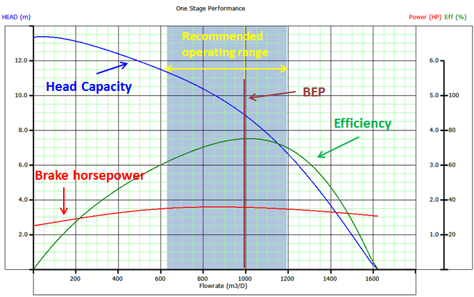
To determine the required number of stages of the pump to produce the anticipated capacity; just divide the Total Dynamic Head (TDH) by the Head developed by Stage.

Refer to the article “ESP design – Step 4: Total Dynamic Head” to review how the TDH is calculated.

The Head developed per stage is deducted from the published performance curve which shows the discharge head developed by the pump. It is an experimental curve given by the manufacturer and obtained with fresh water at 60 F under controlled conditions detailed in API R11 S2. Refer to the articles “Pump Performance Curves – part 01” and “Pump Performance Curves – part 02” for more details.

Once calculated, divide the TDH by the Head developed per stage to get the Total Number of Stages required to produce the anticipated capacity.

Total Stages = TDH / [(Head / stage)]

Continue reading

Updated list of API and ISO Standards for ESP

In this article, the last updated list of API & ISO standards for electrical submersible pump is presented. These standards can be considered as reference documents as well as a basis for training classes in the subject of electrical submersible pump.

Continue reading