The electric submersible motor is simple in construction, rugged and reliable. In this article, the ESP motor compounds are detailed as well as their main functions.
Introduction to ESP motor:
- ESP motor is installed below the motor seal and above the downhole sensor. In cases where a downhole sensor is not installed, the motor is installed at the very bottom of ESP string, generally attached to a motor guide.
- ESP motor is an induction motor, two poles, three phases, squirrel cage type stator winding filled with specific motor oil, high dielectric strength (> 28 KV). The motor is rated for a specific horsepower, voltage, & current. Its role is to drive the downhole pump and seal section.
- The ESP motor rotates at approximately 3500 RPM at 60 Hertz. The difference between actual and the synchronous speed (3,600 RPM) is called “motor slippage” and it is due to losses inside the motor. The actual RPM is usually noted on the motor nameplate (example: 3500 RPM / 60 Hz – 2917 RPM / 50 Hz).
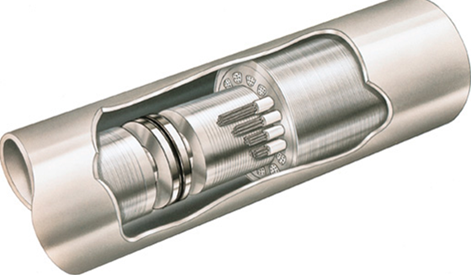
- The ESP motor is constructed of rotors and bearings stacked on the shaft and loaded in a wound stator, the motor compounds will be detailed in the next section.
- The motor contains synthetic dielectric mineral oil for lubrication, insulation, and for the homogeneous distribution of the heat generated inside the motor (cooling). Heat is then drawn off by the produced fluid past the housing OD on the way to the intake.
NB: ESP motor is close to the same design type as motors used on beam pumping units. Of course, it must be small in diameter in order to fit inside oil well casing sizes.
Continue reading →


