ESP submersible pumping system

The ESP submersible pumping system consists of both downhole and surface components. The surface components are transformers, motor controllers, junction box and wellhead.

The wellhead accommodates the passage of the power cable from the surface to the wellbore.

The main down-hole components are the motor, seal, pump, and cable. Additional accessory equipment may include the gas separators, check and drain valves, cable bands and protectors, and downhole sensors.

Technologies, types, recommended practices and selection criteria of each compound of the ESP pumping system are discussed in the following list of 22 posts.

ESP Pump:

01- Submersible Pump System Overview

02- Centrifugal Pump ( ESP Pump)

03- ESP: Pump Stage

04- Pump impeller types

05- Pump Performance Curves – part 01

06- Pump Performance Curves – part 02

07- Pump Construction: Compression Pump vs. Floater Pump

08- Pump Shaft

Pump Intake:

09- Pump Intake

10- ESP Motor Shroud: Applications, Configurations and Selection Criteria

11- ESP: Gas handling device

Seal Section:

12- Motor Seal

ESP Motor:

13- ESP Motor

ESP Cable:

14- ESP Cable

15- Power losses in cables

16- Motor Lead Extension

17- ESP Power Cable Accessories

Motor Controller:

18- ESP Motor Switchboard

19- Variable Frequency Drive Basics

Transformer:

20- Introduction to transformer: How it works?

Wellhead Equipment:

21- Wellhead Equipment for ESP

Accessory Equipment:

22- ESP Accessory Equipment

Pump Shaft

The pump shaft is coupled to the motor shaft through the intake and seal shafts. It transmits the rotary motion from the motor to the impellers of the pump stage. Care must be taken when selecting the shaft material for each application. There are two main considerations: Shaft Strength and Well Fluid Composition.

The diameter of the shaft is minimized as much as possible because of the restrictions placed on the pump outside diameter. The pump power requirements determine if a normal, high-strength, or ultra-high-strength shaft is needed. Most manufacturer’s catalog information specifies what each shaft can handle.

The well fluid composition determines what metallurgy should be used (depends on corrosion protection required).

Shaft Bushings and Shaft Stabilizer Bearing:

Operating a pump outside the manufacturers recommended operating range for extended periods of time will cause excessive wear on the pump stages due to down thrust or up thrust. Thrust wear causes the shaft to vibrate and transfer adverse vibration pulses to other system components, such as the motor protector where eventual fluid entry into the motor may result in a motor burnout.

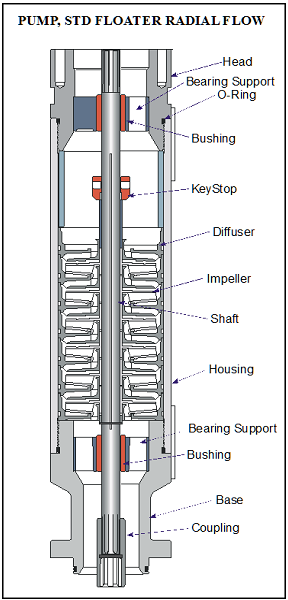
To stabilize and support the shaft, most pumps contain two shaft bushings; one at the top and one at the bottom of the pump housing. Pump shafts may be up to 30-feet in length supported with one or two shaft bearings, depending on the manufacturer. The hub and wear rings on the impeller function as journal bearings against the diffuser. Because journal bearings are made from Ni-resist they tend to be very soft and susceptible to abrasion wear. To mitigate radial wear problems shaft stabilizer bearings can be used.
Continue reading

Compression Pump vs. Floater Pump

There are mainly two designs of electrical submersible pump stages widely used by ESP’s service companies: 

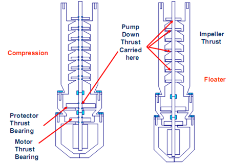
  • Fixed impeller or compression pump design: every impeller is fixed to the shaft and is not free to move up and down. Hence, it cannot move without the shaft moving. All the impellers are “compressed” together to make one rigid body.
  • Floating stage design: each impeller in a floater pump is free to move up and down on the shaft within the confines of the diffuser as depicted in the following Figure. The thrust washers on the impeller support the stage thrust. The amount of thrust varies with liquid rate (the amount of fluid being pumped).

Continue reading