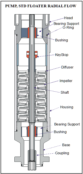
The pump shaft is coupled to the motor shaft through the intake and seal shafts. It transmits the rotary motion from the motor to the impellers of the pump stage. Care must be taken when selecting the shaft material for each application. There are two main considerations: Shaft Strength and Well Fluid Composition.
The diameter of the shaft is minimized as much as possible because of the restrictions placed on the pump outside diameter. The pump power requirements determine if a normal, high-strength, or ultra-high-strength shaft is needed. Most manufacturer’s catalog information specifies what each shaft can handle.
The well fluid composition determines what metallurgy should be used (depends on corrosion protection required).
Shaft Bushings and Shaft Stabilizer Bearing:
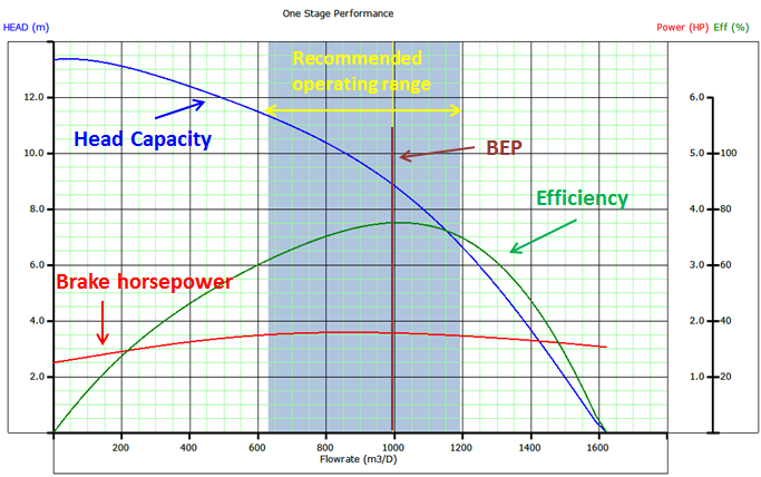
Operating a pump outside the manufacturers recommended operating range for extended periods of time will cause excessive wear on the pump stages due to down thrust or up thrust. Thrust wear causes the shaft to vibrate and transfer adverse vibration pulses to other system components, such as the motor protector where eventual fluid entry into the motor may result in a motor burnout.
To stabilize and support the shaft, most pumps contain two shaft bushings; one at the top and one at the bottom of the pump housing. Pump shafts may be up to 30-feet in length supported with one or two shaft bearings, depending on the manufacturer. The hub and wear rings on the impeller function as journal bearings against the diffuser. Because journal bearings are made from Ni-resist they tend to be very soft and susceptible to abrasion wear. To mitigate radial wear problems shaft stabilizer bearings can be used.


