Y-tool system – A solution to enable well access below ESP

The Y-tool is a solution to enable production-logging and well intervention below a working ESP at any point in time during production without pulling the completion string. The Y-tool is installed on the production tubing, providing two separate conduits. One conduit concentric with the production tubing and enables access to the reservoir below the ESP. The second conduit is offset and used to support the ESP system. Flow rates in different perforation intervals and other valuable geophysical information could be collected for production optimization and enhanced recovery plans.

With an ESP Y-tool in place, Operators are able to carry out wireline or coiled tubing logging, memory gauge deployment, tubing-conveyed perforation, well treatment and stimulation operations, effectively managing production operations and reservoir performance without pulling the ESP, dual ESP installation and bridge plug setting for water shutoff, etc.

Wireline or coiled tubing plugs can be used to seat in a nipple profile in the Y-tool to enable intervention or logging operation without retrieval of the completion. If required, the ESP can be run with these plugs in place to perform production logging or other well interventions.


Continue reading

Pump Shaft

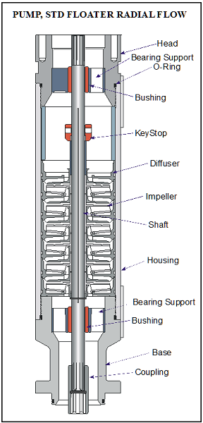
The pump shaft is coupled to the motor shaft through the intake and seal shafts. It transmits the rotary motion from the motor to the impellers of the pump stage. Care must be taken when selecting the shaft material for each application. There are two main considerations: Shaft Strength and Well Fluid Composition.

The diameter of the shaft is minimized as much as possible because of the restrictions placed on the pump outside diameter. The pump power requirements determine if a normal, high-strength, or ultra-high-strength shaft is needed. Most manufacturer’s catalog information specifies what each shaft can handle.

The well fluid composition determines what metallurgy should be used (depends on corrosion protection required).

Shaft Bushings and Shaft Stabilizer Bearing:

Operating a pump outside the manufacturers recommended operating range for extended periods of time will cause excessive wear on the pump stages due to down thrust or up thrust. Thrust wear causes the shaft to vibrate and transfer adverse vibration pulses to other system components, such as the motor protector where eventual fluid entry into the motor may result in a motor burnout.

To stabilize and support the shaft, most pumps contain two shaft bushings; one at the top and one at the bottom of the pump housing. Pump shafts may be up to 30-feet in length supported with one or two shaft bearings, depending on the manufacturer. The hub and wear rings on the impeller function as journal bearings against the diffuser. Because journal bearings are made from Ni-resist they tend to be very soft and susceptible to abrasion wear. To mitigate radial wear problems shaft stabilizer bearings can be used.

Continue reading

Centrifugal Pump ( ESP Pump)

Pump Theory:

The term “centrifugal pump” has been used to describe a wide variety of pumping applications and designs throughout the years. A Centrifugal Pump is a machine that moves fluid by spinning it with a rotating impeller in a diffuser that has a central inlet and a tangential outlet.  The path of the fluid is an increasing spiral from the inlet at the center to the outlet tangent to the diffuser. The fluid rotational motion is the result of the concept of centrifugal forces.

The pressure (head) develops against the inside wall of the diffuser because of the curved wall forces fluid to move in a circular path.

Continue reading

ESP design – Step 6: Optimum Size of Compounds

ESP compounds have different sizes and can be assembled in a variety of combinations. These combinations must be carefully determined to operate the ESP with production requirement, downhole conditions, material strength and temperature limits, etc. to select the optimum size of compounds.

Pump:

To determine the required number of stages of the pump to produce the anticipated capacity; just divide the Total Dynamic Head (TDH) by the Head developed by Stage.

Refer to the article “ESP design – Step 4: Total Dynamic Head” to review how the TDH is calculated.

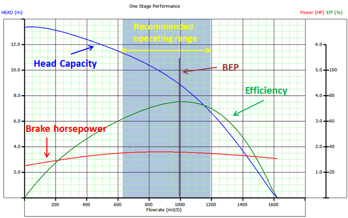
The Head developed per stage is deducted from the published performance curve which shows the discharge head developed by the pump. It is an experimental curve given by the manufacturer and obtained with fresh water at 60 F under controlled conditions detailed in API R11 S2. Refer to the articles “Pump Performance Curves – part 01” and “Pump Performance Curves – part 02” for more details.

Once calculated, divide the TDH by the Head developed per stage to get the Total Number of Stages required to produce the anticipated capacity.

Total Stages = TDH / [(Head / stage)]

Continue reading

ESP design – Step 5: Pump Type

In order to select the most suitable pump, Refer to the pump selection data table in the manufacturer’s catalog for pump type, range and pump performance curve. Based on expected fluid production rate and casing size, select the pump type which will be operating within the recommended operating range and nearest to the pump’s peak efficiency.

When two or more pump types have similar efficiencies at the desired production rate, the following recommendations should be considered to select the most adaptable pump to the well conditions:

The shape of the pump performance curve:

The  ability  of  a  pump to  adapt to  changes in  well  performance  depends  on  the characteristic  shape of  the pump performance  curve. A pump with a steep characteristic (i.e.  large  change  in  head with  respect  to  flow  rate)  is  less  suited  to  a well with  poorly defined  inflow  performance  (IPR),  especially  if  it  is  intended  to  produce  with  a  fixed drawdown.  For  such pumps,  a  small  loss  in  IPR  translates  to  a  large  fall  in pump  intake pressure and may result in gas locking. Conversely, the head produced by a pump with a flatter characteristic will change less for a given  change  of  flow  rate  and  can  therefore  be  used  over  a wider  variety  of  IPR’s with limited changes in intake pressure.

Refer to the article “Pump Performance Curves – part 02” for more details.

Continue reading