


The motor switchboard, as shown in Figure below, provides the means for turning the pump motor on and off, and provides electrical protection for the motor and cable.
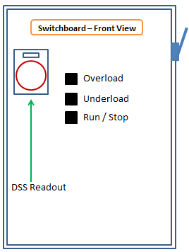
If we start at the line side of a switchboard and move through to the load side, we will find something similar to the Switchboard shown in the figure below.
Manual disconnect (switch):
This switch is used to disconnect the controller from the main power supply after the motor has been stopped.
Fuses:
Connected below the disconnect switch and provide interrupting capability for short circuit conditions that might develop in the motor or output wiring.
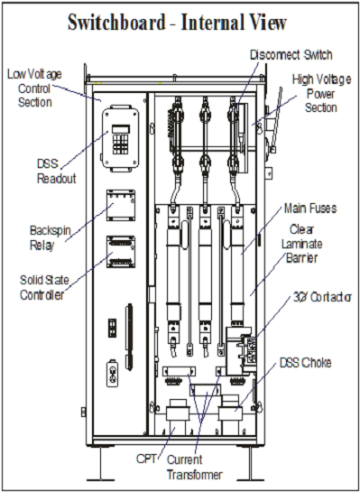
Switch board – Internal View (Source: GE Oil & Gas, Basic ESP Sizing Manual)
Current transformers (CT’s) and the potential transformer (PT):
These devices allow special controls to monitor the amperage and voltage supplied to the motor. Depending on the complexity of the controls, there may be CT’s and PT’s on all three phases. The switchboard will work quite well as a starter without any of the CT’s or PT’s, but its ability to provide protection will be very limited.
Contactor/Motor Starter:
The contactor is located after the PT’s and CT’s and is the device that connects and disconnects the motor from the power source. Connected to the contactor is the output cable to the junction box and on to the wellhead and the motor.
Low Voltage Control Section (left hand portion of the above figure: Switch board – Internal View):
This is what signals the power contactor to operate. It also responds to the manual inputs of start and stop. Then, depending upon the sophistication of the controller, it may perform the following:
- Sensing of an overload and then stopping.
- Sensing a motor underload condition and stopping.
- Automatically restart the unit after an under-load shutdown or power outage when the time has expired.
- Stopping on command from an external set of contacts.
- Detecting poor incoming voltage conditions and stopping. (Loss of phase, low voltage, phase reversal.)
- Data/control communications functions.
Finally, the switchboard will generally have a recording ammeter. This ammeter records Motor Current versus Time. These amp charts are one of your best tools in solving pump production problems.
You May Also Like…
