Motor Seal

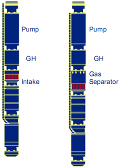
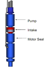
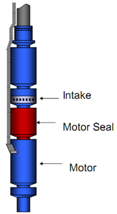
The Motor seal is installed below the intake and above the electric motor. It is also named: Equalizer, balance chamber, or Protector. Seal section types, functions, components, and applications are detailed in this article.

In addition to the main function of transferring the motor torque to the pump shaft, the seal section performs four primary functions (Equalization, Expansion, Isolation, & “Aabsorbsion):

  • Equalizes the pressure in the wellbore with the pressure inside the motor,
  • Provides area for motor oil expansion volume (induced by temperature changes in the motor),
  • Isolates the well fluid from the clean motor oil,
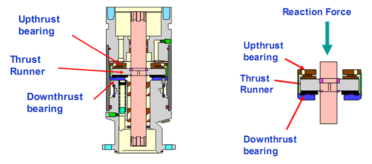
  • Absorbs the pump shaft thrust load (it houses the thrust bearing that carries the axial thrust developed by the pump, it can either be upthrust or downthrust, depending on the pumping conditions – obviously, for fixed impeller type only).


PS: The motor, pump and seal are often submerged below several thousand feet of fluid. The seal section allows the pressure in the motor and the annulus to equalize, so that there is very little pressure across the shaft seals or the pothead connection.

PS: When selecting the protector, we need to be certain that the protector shaft is capable of delivering the full torque required without exceeding its yield strength which could result in a broken shaft.

Continue reading

ESP: Gas handling device

Gas  handling  devices  may  be  a  better  alternative  for  wells  prone  to  high  free  gas, slugging, foams and emulsions. These are essentially centrifugal pumps with large stages, mixed  (or  axial)  impellers,  large  vane  openings,  steep  vane  exit  angles  and  sometimes include multiple  vanes. 

Instead of separating, their purpose is to break large gas bubble into smaller ones thereby reducing the risk of gas locking and making it easier for gas to be re-absorbed into solution, and to homogenize the gas with liquid phases, prior to entering the pump intake.

An additional benefit of gas handlers is, because more gas is retained in the flow stream, this gas is then available to help lift fluids in the tubing above the ESP discharge head thereby reducing hydraulic horsepower requirements.

Applications: A Gas Handler is generally considered if the Free Gas Percentage at the intake of the pump is from 30% to 60% by volume.

Continue reading

ESP: Pump Intake

As the name suggests “ Pump Intake ” is where the well fluid enters the Submersible Pumping System. Care should be taken when designing a submersible pump intake because it is such a vital point in the system that when not designed properly may create all kinds of problems.

There are three types of intake Sections:

  • Standard Intakes or BOI (bolt on intake),
  • Integral (manufactured as part of the pump),
  • Gas Separators (static and rotary gas separators).

Standard and Integral Intakes:

Standard intakes (BOI and integral) do not separate gas.  Some gas separation might occur, but it will only be natural separation due to some of the gas not turning and going into the intake when the rest of the fluid does. Therefore, the standard intake is for wells that produce with a very low free gas to liquid ratio. The amount of free gas by volume at pump intake conditions should be no more than 10% to 15% by volume (depends if it is a radial or mixed flow stage)
                           

Usually, the pump intake is a separate component that bolts onto the bottom of the pump section. Occasionally, the pump is built in either a lower tandem or single configuration. In these cases, the pump intake as an integral part of the pump assembly.

Continue reading