Motor Lead Extension

The Motor Lead Extension is a “special power cable extending from the pothead on the motor to above the end of the pump where it connects with the power cable (API RP 11S4).

A low-profile cable (flat configuration) is usually needed in this area due to limited clearance between the pump housing and the well casing”.

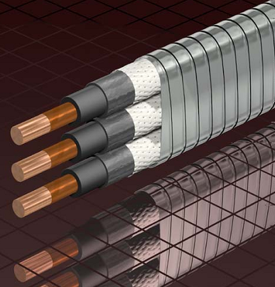
It is recommended to select a length at least 6 ft. (1.8 m) longer than the upper end of the pump. The length of MLE has to be select in a way to avoid a splice over a tubing collar. Doing so could allow the cable to catch on the wellbore casing and damage the equipment.

The motor lead extension operates under extremely adverse conditions. This is due to the restricted size, the high mechanical stresses, and the high temperatures involved. Because of these effects, motor lead extensions are usually replaced every time a cable is reused.

Continue reading

Power losses in cables

Cable power losses or power drop are due to the conductor resistance heating that occurs when current flows. These cable losses are more often called KW losses or I²R losses. This is expressed by the following formula:

Power losses = 3 × (I²R) /1000

Where: Power losses in kW units, I is the current (in amps) and R (in ohms) is the average conductor resistance.

How to lower the resistance in the cable?

Power lost in a cable depends on the cable length, cable size and the current through the cable. Therefore, there are three ways to lower the resistance in the cable:

  • Shorten the length of the cable,
  • Increase the size of the conductor,
  • Decrease the current through the cable.

Continue reading

ESP Diagnostic Diagram


ESP Diagnostic Diagram

By Burney Waring, Consultant at WaringWorld, Inc.

One of my clients brought this diagram to my attention recently. The paper, by Petroleum Development Oman and Engineering Insight Ltd of Aberdeen, was very useful and included an especially useful diagram, but the diagram was not so easy to read or print in a larger size. I tried to improve the image so that it would be even more helpful. All credit goes to the authors and their paper IPTC 17413 2014, available on SPE’s OnePetro.

Here is the full size diagram:

Continue reading

ESP Motor Shroud: Applications, Configurations and Selection Criteria

The ESP motor Shroud is a cylinder fitted around the Motor, Protector and Intake sections of an ESP. It is designed to provide cooling to the motor when fluid velocities are below minimum by reducing the annular area between the ESP and the casing bore.

The Shroud is simply constructed with a length of tube long enough to swallow the Motor, Protector and Intake sections, and is bolted with a split clamp unit to first ESP neck located above Intake. The MLE cable is run through the shroud. The shroud assembly is made up of a jacket (a length of casing or pipe), a hanging clamp and sealing retainer for the top, and a centralizer for the bottom.

Above the Shroud, an MLE Clamp is normally fitted to secure the MLE to the Discharge Head. At the bottom end, a Centralizer Guide is fitted to help secure the ESP section within the Shroud. The Shroud can be manufactured from a thin casing, stainless steel or fiberglass.

Continue reading

Pump Shaft

The pump shaft is coupled to the motor shaft through the intake and seal shafts. It transmits the rotary motion from the motor to the impellers of the pump stage. Care must be taken when selecting the shaft material for each application. There are two main considerations: Shaft Strength and Well Fluid Composition.

The diameter of the shaft is minimized as much as possible because of the restrictions placed on the pump outside diameter. The pump power requirements determine if a normal, high-strength, or ultra-high-strength shaft is needed. Most manufacturer’s catalog information specifies what each shaft can handle.

The well fluid composition determines what metallurgy should be used (depends on corrosion protection required).

Shaft Bushings and Shaft Stabilizer Bearing:

Operating a pump outside the manufacturers recommended operating range for extended periods of time will cause excessive wear on the pump stages due to down thrust or up thrust. Thrust wear causes the shaft to vibrate and transfer adverse vibration pulses to other system components, such as the motor protector where eventual fluid entry into the motor may result in a motor burnout.

To stabilize and support the shaft, most pumps contain two shaft bushings; one at the top and one at the bottom of the pump housing. Pump shafts may be up to 30-feet in length supported with one or two shaft bearings, depending on the manufacturer. The hub and wear rings on the impeller function as journal bearings against the diffuser. Because journal bearings are made from Ni-resist they tend to be very soft and susceptible to abrasion wear. To mitigate radial wear problems shaft stabilizer bearings can be used.

Continue reading