ESP design – Step 7: Electric Cables

The AC current is carried from the surface to the motor using either copper or aluminum cable conductors. For ESP applications, four sizes of conductors have been standardized: #1, #2, #4 and #6 AWG (AWG stands for “American Wire Gauge”). Electric Cables are available in either flat or round configurations.

An electric submersible cable is mainly compounded by a cable conductor, insulation, jacket, braid & covering and armor. These cable compounds are for protection against corrosive fluids and severe environments.

Cable selection involves the determination of Cable Size, Type and Length.

Cable Size:

The proper cable size is dependent on combined factors of voltage drop, amperage and available space between tubing collars and casing.
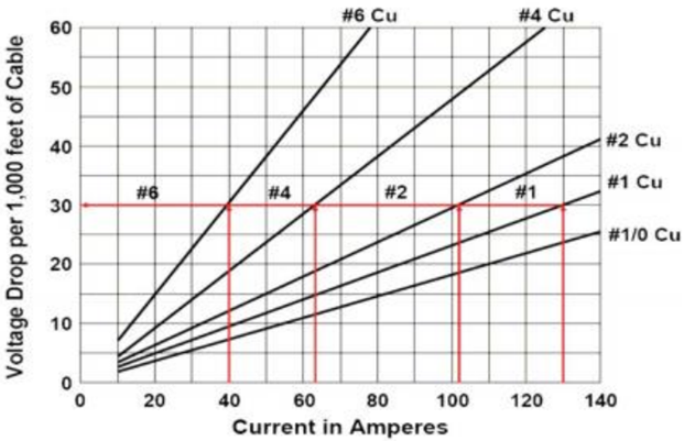
  • Cable Voltage Drop:

The following graph shows an example of Cable Voltage drop plot to determine the voltage drop in cable. At the selected motor amperage and the given downhole temperature, the selection of a cable size that will give a voltage drop of less than 30 volts per 1000 feet is recommended. This curve will also enable you to determine the necessary surface voltage (motor voltage plus voltage drop in cable) required to operate the motor.

Continue reading

ESP design – Step 6: Optimum Size of Compounds

ESP compounds have different sizes and can be assembled in a variety of combinations. These combinations must be carefully determined to operate the ESP with production requirement, downhole conditions, material strength and temperature limits, etc. to select the optimum size of compounds.

Pump:

To determine the required number of stages of the pump to produce the anticipated capacity; just divide the Total Dynamic Head (TDH) by the Head developed by Stage.

Refer to the article “ESP design – Step 4: Total Dynamic Head” to review how the TDH is calculated.

The Head developed per stage is deducted from the published performance curve which shows the discharge head developed by the pump. It is an experimental curve given by the manufacturer and obtained with fresh water at 60 F under controlled conditions detailed in API R11 S2. Refer to the articles “Pump Performance Curves – part 01” and “Pump Performance Curves – part 02” for more details.

Once calculated, divide the TDH by the Head developed per stage to get the Total Number of Stages required to produce the anticipated capacity.

Total Stages = TDH / [(Head / stage)]

Continue reading

ESP design – Step 5: Pump Type

In order to select the most suitable pump, Refer to the pump selection data table in the manufacturer’s catalog for pump type, range and pump performance curve. Based on expected fluid production rate and casing size, select the pump type which will be operating within the recommended operating range and nearest to the pump’s peak efficiency.

When two or more pump types have similar efficiencies at the desired production rate, the following recommendations should be considered to select the most adaptable pump to the well conditions:

The shape of the pump performance curve:

The  ability  of  a  pump to  adapt to  changes in  well  performance  depends  on  the characteristic  shape of  the pump performance  curve. A pump with a steep characteristic (i.e.  large  change  in  head with  respect  to  flow  rate)  is  less  suited  to  a well with  poorly defined  inflow  performance  (IPR),  especially  if  it  is  intended  to  produce  with  a  fixed drawdown.  For  such pumps,  a  small  loss  in  IPR  translates  to  a  large  fall  in pump  intake pressure and may result in gas locking. Conversely, the head produced by a pump with a flatter characteristic will change less for a given  change  of  flow  rate  and  can  therefore  be  used  over  a wider  variety  of  IPR’s with limited changes in intake pressure.

Refer to the article “Pump Performance Curves – part 02” for more details.

Continue reading

ESP design – Step 4: Total Dynamic Head

The step4 of the ESP design consists on determining the total dynamic head required to pump the desired capacity. It is common to simplify the procedure by combining or summarizing the additional energy that the pump must supply into a single term, Total Dynamic Head (TDH). TDH is a summation of the net vertical distance fluid must be lifted from an operating fluid level in the well, the frictional pressure drop in the tubing and the desired wellhead pressure.

TDH = HD + HF + HT

  • TDH: total dynamic head in feet (meters) delivered by the pump when pumping the desired volume.
  • HD: vertical distance in feet (meters) between the wellhead and the estimated producing fluid level at the expected capacity.
  • HF: the head required to overcome friction loss in tubing measured in feet (meters).
  • HT: the head required to overcome friction loss in the surface pipe, valves, and fittings, and to overcome elevation changes between wellhead and tank battery.

PS: HT is normally measured in gauge pressure at the wellhead. It can be converted to head, in feet (meters) as follows: HT = (psi / (0.433 psi/ft x sp. gr.)

Continue reading

ESP design – Step 3: Gas Calculations

The presence of free gas in the tubing above the pump changes the fluid density, consequently reduces the required discharge pressure. Also the performance of centrifugal pumps is considerably affected by the presence of free gas in the pumped fluid. The pump starts producing lower than normal head as the produced GLR (Gas to Liquid Ratio) at the pumping conditions increases beyond a critical value. The critical value of the ratio or percentage of free gas present at the pump intake to the total volume of fluid depends on the pump impeller design (typical critical values are shown in the article “ESP: Gas handling device “). Therefore, it is essential to determine the percentage of free gas by volume at the pumping conditions in order select the proper pump and gas handling device (if required).

Percentage of free gas by volume:

Assuming that Solution GOR (Rs), Gas Volume Factor (Bg) and Oil Formation Volume Factor (Bo) are known, the total volume of fluids and the percentage of free gas released at the pump intake should be calculated.

Continue reading