ESP design – Step 2: Production Capacity

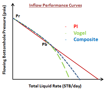
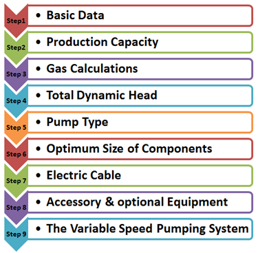
Once the first step “Collect basic data” is performed, we pass to the ” step 2: Production Capacity “ of the ESP Nine Step Design Procedure. It consists on predicting the well inflow performance which represents the relationship between pressure and flow rate at the well face of an individual well and it is physically defined as the well flowing bottom-hole pressure (Pwf) as a function of production rate. It describes the flow in the reservoir.

Many inflow performance relationships (IPR’s) are described in the literature. In this article, we will briefly present three of the most widely used IPR’s to describe the well performance:


Continue reading

ESP design – Step 1: Basic data

As described in the previous article ESP nine step design procedure, Centrilift has established a nine-step procedure to design the appropriate electrical submersible pump. The first step of this ESP design procedure, and certainly the most important step, consists on collecting the basic data. This is the most important step because all the others design steps will depend on the basic data selected in step 1. If the basic data quality is good the design will be good and the ESP will operate at its optimum conditions. Otherwise, if the input data quality is poor the design will usually be marginal.

A list of required data is outlined next:

ESP Nine Step Design Procedure

Centrilift has established a nine-step procedure to design the appropriate electrical submersible pump in order to have an efficient and cost-effective performance. This article gives an overview of the ESP nine step design procedure and outlines the procedure as a manual process to illustrate the design steps. Each of the nine steps will be explained in detail in the next articles.

Specific examples will be worked through in each step of the ESP design.

This nine step procedure is a basic hand-design of simple water and light crude oil. For more complicated well conditions, such as high GOR, viscous oil, high-temperature wells, there are many of available ESP design software (e.g. Prosper software – Product of Petroleum Expert; Pipesim software – Product of Schlumberger; Autograph PC software – Product of Baker Hughes; Solution Sizing Software – Product of General Electric; DesignRite Software – Product of Schlumberger). The fashion of use of each of these ESP design software will be presented and explained in detail in upcoming articles in our website.

Affinity Laws

The affinity laws, also known as “Pump Laws”, for pumps are used to express the relationship between variables involved in pump performance (such as head, flow rate, shaft speed) and power.

According to the affinity laws, the following relationships exist between the actual speed of the centrifugal pump and its most important performance parameters:

  • The flow rate of a pump changes directly proportional to its operating speed.
  • The head developed by the pump changes proportionally to the square of the speed.
  • The brake horsepower required to drive the pump changes proportionally to the cube of the speed.
  • The efficiency of the pump does not change with speed changes.

Continue reading

Pump Performance Curves – part 02

In the previous article “Pump Performance Curves – part 01“, we have discussed how pump performance curves are obtained? How there are plotted? What are the downthrust and the upthrust? and what is the recommended operating range of the pump? In this article, pump performance curve is further detailed and we will answer the following two questions :

  • How the shape of the pump performance curve is related to changes in well performance?
  • What are the tolerance limits of performance data?

Shape of the pump performance curve:

The  ability  of  a  pump  to  adapt  to  changes  in  well  performance  depends  on  the characteristic  shape of  the pump performance  curve.

Continue reading