Pump Performance Curve – part 01

The pump performance curves characterize the performance of ESP pumps. This article will detail the technical aspects related to these curves and will answers the following questions: How pump performance curve is obtained? How to plot it? What are the downthrust and the upthrust? What is the recommended operating range of the pump?

Pump Curve:

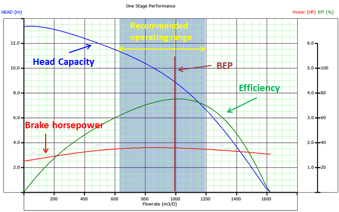
The published pump performance curve describes the performance of particular pump (or stage). It shows the discharge head developed by the pump, brake horsepower (power consumption curve), and efficiency of the pump as a function of flow rate. It is an experimental curve given by the manufacturer and obtained with freshwater at 60 °F (S.G. = 1) under controlled conditions detailed in API RP11 S2. These curves are commonly available for both 50 Hz and 60 Hz operation and must represent the operation of one or more stages of each pump curve (the number of pump stages must be clearly indicated on the pump chart).

Typical Pump Curve

  • The left vertical axis is scaled in feet and meters of head (or lift).
  • The bottom horizontal axis is scaled in bbl/d and m3/d.
  • The curve labeled Head-Capacity defines the lift (or head) the impeller can produce at all of the available flow rates.
  • The first vertical axis on the right is scaled in horsepower. It is based on pumping water with a specific gravity of 1.00.

Continue reading

Total Dynamic Head Calculation

In this article “ Total Dynamic Head Calculation ”, the concept of the dynamic head is further detailed. As discussed in the previous article titled: “Total Dynamic Head (TDH)”, TDH is the sum of three basic components:

  1. Net Vertical Lift (NL) = is the net distance where the fluid must be lifted,
  2. Tubing Friction Loss (TFL) = Flow disturbance in the tubing string during pumping process,
  3. Tubing Head Pressure (THP) = Pressure which the unit must pump against (back pressure caused by choking on well head).

Continue reading

Total Dynamic Head (TDH)

To properly select the pump, well performance must be estimated. Fundamentally, well performance estimates define what additional energy (i.e., volumetric flow rate and differential pressure or head) must be supplied by the pump to deliver a desired stock tank flow rate (API RP11 S4).

It is common to simplify the procedure by combining or summarizing the additional energy that the pump must supply into a single term, Total Dynamic Head (TDH). TDH is a summation of the net vertical distance fluid must be lifted from an operating fluid level in the well, the frictional pressure drop in the tubing and the desired wellhead pressure.

TDH = HD + HF + HT

Continue reading

Variable Frequency Drive Basics

In this article, Variable Frequency Drive (also, named: Variable Speed Drive) basics are presented in a simple and easy way with explanation graphs. To understand how the Frequency Speed Controller operates, it is necessary to understand how the VSD supplies variable voltage and frequency for speed control.

The below block diagram illustration depicts a typical three-phase AC variable speed drive system. It has three main components: an Operator Control, a Drive Controller, and an AC Motor.

An Operator Control device provides a means to start and stop the motor and adjust the operating speed. The Drive Controller consists of a variety of components that work together to convert an AC input into a frequency and voltage output necessary to change the speed of an AC motor.

Main sections of a Variable Frequency Drive:

The converter section:

This section converts the incoming 3-phase AC voltage to DC voltage. The converter is essentially a 3-phase, full wave rectifier with Silicon Control Rectifiers, a specialized type of control diode, in the bridge.

The following video explains what SCR is and how it works:

Continue reading

Introduction to transformer: How it works?

The transformer is used to convert the incoming voltage at the location to the correct voltage (for the submersible motor in case of ESP). Transformer selection is based on mainly 4 parameters:

  • Power rating in KVA (Kilo Volt Amperes),
  • Primary voltage,
  • Secondary voltage,
  • Tap arrangement.

Power rating in KVA for three phase transformer:

The calculation of power rating in KVA for a Three Phase Transformer is based on Winding Voltage and Amperage information. The simple formula to calculate the rating of three phase transformers is:

KVA = (√3. V x I) /1000

Refer to the post titled “How to Calculate the Required KVA Rating for three Phase Transformers? ” for more details.

Continue reading