


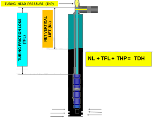
In this article “ Total Dynamic Head Calculation ”, the concept of the dynamic head is further detailed. As discussed in the previous article titled: “Total Dynamic Head (TDH)”, TDH is the sum of three basic components:
- Net Vertical Lift (NL) = is the net distance where the fluid must be lifted,
- Tubing Friction Loss (TFL) = Flow disturbance in the tubing string during pumping process,
- Tubing Head Pressure (THP) = Pressure which the unit must pump against (back pressure caused by choking on well head).
- Net Vertical Lift:
Net Vertical Lift is the vertical distance in the tubing that the fluid must be lifted to get to the surface. The energy required to lift the fluid can be determined by the equation:
Work = mgΔh
Where:
- m = mass of fluid
- g = acceleration due to gravity
- Dh = height the fluid is lifted
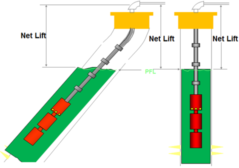
NB: That the vertical lift only depends on where the fluid level is. From the Net Lift stand point, it makes no difference where the pump is set.
NB: Regardless of what is the angle of the well, the vertical lift does not change (Δh is the same).
Example:
Assume a given fluid level of 4000 feet (TVD) from surface, so:
Net Vertical Lift = 4000 feet
Remember if the well is deviated, the total measured distance (MD) from surface could be much greater. But, since the work done in moving the fluid sideways is zero, only the vertical distance matters.
- Tubing Friction Loss:
Friction is an energy loss due to viscous shear of the flowing fluid. In a fluid, molecules are free to move past each other but there will be a little resistance. This resistance is due to shear forces which must be overcome. The higher the shear forces, the higher the viscosity.
In a single phase fluid, most of the liquid is moving along together so there is not much shear in the liquid itself and this friction can usually be ignored. The walls of the pipe, however, will tend to “stick” to the fluid. So, shear forces between the pipe and the fluid can be quite large and increase as the velocity of the fluid increases.
The amount of friction can be represented by Friction Factor “f”.
Given “f”, we can calculate pressure lost using the following formula:
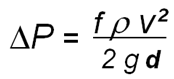
Where: ΔP = pressure loss r = fluid density
v = fluid velocity g = gravity constant
d = tubing diameter
NB: As the pipe diameter increases, the ΔP decreases as can be seen in the equation. Also, as the pipe diameter increases, the velocity V decreases by the square of the diameter change (assuming a constant flowrate), so it is reduced drastically. These two factors mean an increase in pipe diameter has a large impact on decreasing the frictional pressure losses.
Friction loss calculation:
There are many charts available for determining friction losses:
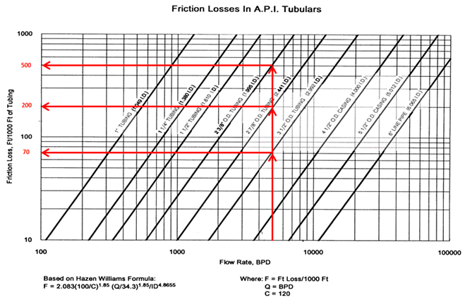
How to use the chart?
Let say for example, we have a total tubing length (pump setting depth MD) of 6500 feet – and we want to produce 5000 bpd. And, we have three sizes of tubing: 2-3/8″, 2-7/8″ and 3- ½” available in stock.
What will the friction be for each size?
- Total Friction Loss on 6500 ft of 2 3/8” tubing = 500 x (6500 ft/ 1000) = 3250 ft.
- Total Friction Loss on 6500 ft of 2 7/8” tubing = 200 x (6500 ft/ 1000) = 1300 ft.
- Total Friction Loss on 6500 ft of 3 1/2” tubing = 70 x (6500 ft/ 1000) = 455 ft.
- Tubing Head Pressure:
Up to this point, we have been calculating everything in terms of “feet”. This is very convenient when sizing a pump, because pump curves are usually plotted in terms of feet of head which makes it easy to calculate the number of stages.
Let say for example, we have:
- Wellhead pressure = 200 psi
- Water Cut = 60%
- Water specific gravity = 1.07
- Oil API = 30 °API
What is the wellhead pressure in feet?
- Using the API gravity equation, determine oil SG :
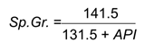
- Oil specific gravity = 0.876
- Find the “composite” specific gravity of the fluid in the well:
(Sp. Gr.)Mixture = [(Sp. Gr.)Water x WC] + [(Sp. Gr.)Oil x (1-WC]
Average SG = (1.07 x 0.6) + (0.876 x 0.40) = 0.992
- Wellhead (feet) also can be determined by the following equation:
Pressure (psi) = 0.433 (psi/ft) x SG x Depth (ft)
0.433 is density of fresh water.
Wellhead (ft) = WHP (psi) / (0.433 x SG)
- Wellhead (ft) = 465.6 ft
- Total Dynamic Head:
Total Dynamic Head = Net Vertical Lift + Tubing Friction Loss + Tubing Head Pressure
Assuming a 3 ½” tubing:
Total Dynamic Head = 4000 + 455 + 465.6 = 4920.6 ft
TDH = 4921 ft
So we would need to design a pump with enough stages to produce 4921 feet of head.
Let’s assume a pump having Lift per stage = 25.1 ft/stage @ BEP, total stage required will be:
Total Stage Required (TSR) = TDH / Lift per stage
TSR = 4921 (ft) / 25.1 (ft/stage)
TSR = 196 stages
- Head Loss Across the Motor:
Consider head loss across the motor, as it is can be a significant factor in obtaining the required result. A heavy casing with a minimal clearance may increase velocity past the motor, but in many cases the decreased clearance can cause a substantial pressure drop which the pump will have to overcome
A simple equation may be used to calculate this loss:
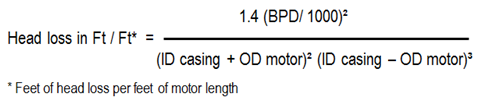
Add the total head loss required for the pump to overcome to the calculated TDH and recalculate the new number of the stages and motor HP required.
