


A good understanding of counterbalance is vital to the successful operation of surface sucker rod pumping units. Poor counterbalance practices can cause early failure of the gear reducer gearing and will result in excessive energy cost.
Non-counterbalanced lever system:
The up-stroke:
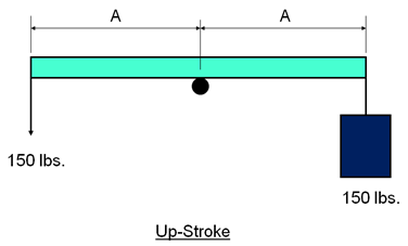
The figure above represents a simple non-counterbalanced lever system. On the up-stroke, by pulling down on the end of a beam, a man is lifting a bucket full of water having a combined weight of 150 lbs.
Note that the upstroke effort of the man is a substantial 150 lbs.
The down-stroke:
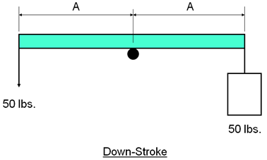
On the down stroke, the water is emptied out and the bucket weights only 50 lbs. During this half of the pumping cycle the man works at a much less rate of 50 lbs.
Counterbalanced System:
The up-stroke:
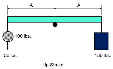
The non-counterbalanced system was a system in which the man had to work very hard over one half of the pumping cycle then very little over the second half of the cycle. The most desirable loading would be to work equally during both halves of the pumping cycle.
If we average the upstroke load and the downstroke load (150+50)/2 = 100 and place a counterbalance weight equal to 100 lbs. at the rear end of the beam then the upstroke effort required of the man is now only 50 lbs.
The down-stroke:
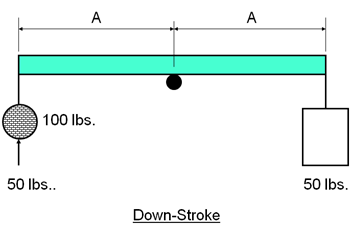
Now, with counterbalance during the downstroke, the man has to push up with an effort of 50 lbs.
By placing 100 lbs. counterbalance weight on the rear end of the beam, the man now work more uniformly throughout the total pumping cycle and require less manpower to lift the fluid.
This example is very similar to the early pumping systems used to pump oil. Weight placed on the rear end of the walking beam provided the counterbalance for the pumping unit.
