


Beam pumping Unit Principles:
A beam pumping unit is a machine for translating rotary motion from a crankshaft to a linear reciprocating motion for the purpose of transferring mechanical power to a down-hole pump.
The purpose, simply stated, of the basic system is to transmit energy from the surface to the downhole pump. The resulting configuration has been referred to as a Sucker Rod Pumping System.
Beam pumping Unit Components:
The beam pumping unit includes:
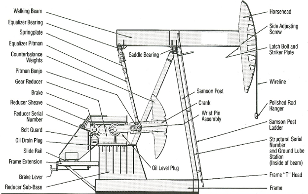
The beam pump structure: defined as all components between the carrier bar and the speed reducer output shaft.
Carrier bar: the part of the pumping unit that supports the load of the sucker rod string through the polished rod clamp.
Horsehead: a component of a beam pumping unit designed to transmit force and motion from the walking beam to the flexible wireline. Its shape is such that the imparted motion is directed vertically above the well head allowing the polished rod to move without undue side loads.
Cranks: driving link in the four-bar linkage of a beam pumping unit that is located between the output shaft of the gear reducer and the pitman link.
Equalizer: connects the pitman links to the rear of the walking beam.
Pitmans: connecting link in the pumping unit mechanism between the cranks and the equalizer.
Samson post bearing: bearing mounted to a fixed location atop the Samson post of the pumping unit that is attached to and provides the fulcrum location for the walking beam.
Speed reducer: a mechanism located between the belt drive and the cranks to transmit rotary power while reducing speed and increasing torque.
Brake: a component of a pumping unit designed to restrain motion in all rotary joints. It is often composed of a disk or drum mounted on the reducer input shaft combined with a mechanism to impart a restraining friction torque.
There are several types of Surface Units that could cover a wide range of applications. Gear Boxes are made of Gear Reducer and a housing which support the torque demand and transmit the rotary movement from the prime mover to the crankshaft of the surface unit. Two prime movers types are used, commonly depending on the power availability: electric motor and/or internal combustion engines. At the wellhead the stuffing box has as main function, avoid damages to the polished rod and prevent oil leaks. The polished rod transmits the reciprocating movement from the surface unit to the sucker rod string.
Classes of Lever Systems:
The forerunners of the modern-day pumping units were introduced about 80 years ago. These were Class I and Class III lever systems:
- Class I Lever System: Gearbox rear–mounted with the fulcrum at mid beam (Conventional).
- Class III Lever System: Gearbox front–mounted with the fulcrum at the rear of the walking beam (Mark II and Air Balanced).
Class I Lever System: Lever system in which the fulcrum (le point d’appui) is located between the load and the applied force or effort. An example of this is a beam pumping unit with the fixed saddle bearing located along the walking beam between the equalizer and the well.
These units may be provided with crank counterbalance or they may have a beam counterbalance, usually steel weights that can move back and forth on the back part of the beam, or they may be a combination of both beam and crank counterbalance.
Conventional Pumping Units are an example of Class I Lever System.
Class III Lever System: Lever system in which the applied force (effort) is located between the load and fulcrum. An example of this is a beam pumping unit with the equalizer located between the fixed Samson post bearing and the well.
This unit with crank counterbalance was introduced in the 1960’s. These units have different motion characteristics. All beam pumping units must use some type of speed reducer between the prime mover and the crank arm of the unit. Most all units use a double reduction gearbox to achieve this slowdown in rpm.
Lufkin Mark II Pumping Units are an example of Class I Lever System.
Reference:
- Spec 11E – Specification for Pumping Units.
You May Also Like…
- Why Rod Lift?
- All what you need to know about sucker rod pumping system
- 10 Types of Rod Pumping Units
- Beam Pumping Unit Principles and Components
- Surface Components of Sucker Rod Pumps in different languages
