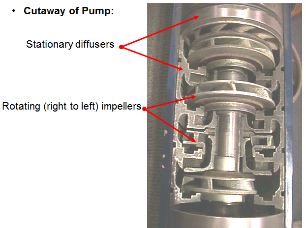
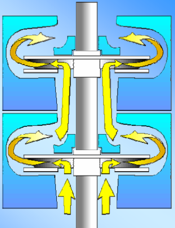
A “ Pump Stage ” consists of an impeller, diffuser and thrust washers. As shown by the following figure, the impellers rotate with the shaft and spin at the RPM of the motor. The stationary diffusers turn the fluid into the next impeller and do not rotate. Pumps are assembled by stacking stages on a shaft and compressing the stack in a housing. A stage will produce a given amount of flow and lift (head) at the motor RPM.
Category Archives: Artificial Lift
Pump impeller types
The pump stages are of a fully enclosed curved vane design, whose maximum efficiency is a function of impeller types and designs. There are two basic types of stages used in oil well submersible pumps: stages with Mixed flow impeller and stages with Radial flow impeller.
The difference between these two types of designs is described by the pump impeller vane angles and the size and shape of the internal flow passages, as depicted in the graphs below.
Gas lifted well: Operations & unloading process
Gas lift operations and unloading procedure are described in the following demonstration video:
In order to further explain all these aspects and more simplify the process, gas lift operations have been described in the next paragraphs:
CO2 Tracer Technology for Surveillance of Gas Lifted Wells
CO2 tracer technology is a low cost effective method to quikly and reliably check if a gas lifted well is producing at its optimum conditions.
Actually, the CO2 tracer survey would detect the operating lift depth, multiple points of injection, tubing leaks.