The pump performance curves characterize the performance of ESP pumps. This article will detail the technical aspects related to these curves and will answers the following questions: How pump performance curve is obtained? How to plot it? What are the downthrust and the upthrust? What is the recommended operating range of the pump?
Pump Curve:
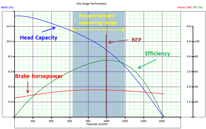
The published pump performance curve describes the performance of particular pump (or stage). It shows the discharge head developed by the pump, brake horsepower (power consumption curve), and efficiency of the pump as a function of flow rate. It is an experimental curve given by the manufacturer and obtained with freshwater at 60 °F (S.G. = 1) under controlled conditions detailed in API RP11 S2. These curves are commonly available for both 50 Hz and 60 Hz operation and must represent the operation of one or more stages of each pump curve (the number of pump stages must be clearly indicated on the pump chart).

Typical Pump Curve
- The left vertical axis is scaled in feet and meters of head (or lift).
- The bottom horizontal axis is scaled in bbl/d and m3/d.
- The curve labeled Head-Capacity defines the lift (or head) the impeller can produce at all of the available flow rates.
- The first vertical axis on the right is scaled in horsepower. It is based on pumping water with a specific gravity of 1.00.
Definitions:
Total head: the difference between the pump outlet and inlet head in feet. As detailed in the article: “Total Dynamic Head (TDH)“, this is the vertical distance, in feet from the pumping fluid level to the centerline of the pressure gauge, plus the pressure gauge reading converted to feet, plus the friction loss between the pump discharge and pressure gauge in feet.
Brake horsepower (BHP): the power required by the pump corrected for a fluid with a S.G. = 1.
Best Efficiency Point (BEP): Defines pump performance parameters at the maximum value on the efficiency curve.
Recommended operating range: located between the maximum and minimum recommended flow rates.
Examples:
From the previous pump performance curve, at 1000 m3/d (Pump BEP) a single pump stage will produce 8.75 m of lift (or head). It requires 1.75 hp if the fluid has specific gravity of 1. For fluid having a specific gravity of 0.85, it only requires 1.49 hp (1.75 x 0.85). From the right most axis, the efficiency is 75%.
Effect of axial forces on the ESP performance:
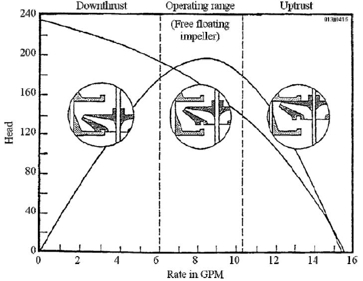
All centrifugal pumps develop axial thrust. Axial thrust is an important factor in establishing the recommended operating range of a centrifugal pump. Refer to following Figure, which depicts a typical thrust curve vs. capacity over the entire range of a particular pump type. It shows where up-thrust and down-thrust occurs in relation to the head capacity curve.
Every centrifugal stage is designed to produce at a certain flow rate range. In addition, there is a best efficiency point (BEP) for every stage. Furthermore, every stage type has a recommended range. In the previous typical pump performance curve, the recommended range is indicated by a blue color area (from 630 to1200 m3/d). Across the operating range, the forces on either side of the impeller shroud are such that they minimize the amount of thrust that would be transmitted to the diffuser pads.

NB: Thrust generated by a multi-stage centrifugal pump is usually supported in one of two ways: Floater Construction or Compression Construction. Both technologies are detailed in the article: “Compression pump vs. Floater pump “.
Conclusion:
In conclusion, any given pump must be operated in the Recommended Operating Range defined by the two boundary rates described previously (downthrust and upthrust limits).
Practical conclusions:
- An ESP pump follows its characteristic curve when delivering the flow rate from zero to a maximum value usually named “open flow” (pump flow rate @ zero head).
- Each flow rate has a unique head capacity.
- The flowrate‐Head capacity curve depends on: the rotational speed of the pump, the diameter, and the shape of the impeller. Changing these parameters affects the head and horsepower curves according to the pump and affinity laws.
- The density of the pumped fluid affects only the power input curve.
- The viscosity of the pumped fluid affects the flow rate, the pump efficiency, and the brake horsepower. The flow rate and efficiency decrease with a simultaneous increase in the power consumption (brake horsepower).


