ESP: Pump Intake

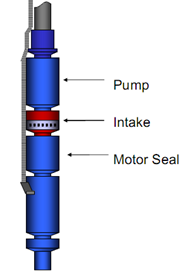
As the name suggests “ Pump Intake ” is where the well fluid enters the Submersible Pumping System. Care should be taken when designing a submersible pump intake because it is such a vital point in the system that when not designed properly may create all kinds of problems.

There are three types of intake Sections:

  • Standard Intakes or BOI (bolt on intake),
  • Integral (manufactured as part of the pump),
  • Gas Separators (static and rotary gas separators).

Standard and Integral Intakes:

Standard intakes (BOI and integral) do not separate gas.  Some gas separation might occur, but it will only be natural separation due to some of the gas not turning and going into the intake when the rest of the fluid does. Therefore, the standard intake is for wells that produce with a very low free gas to liquid ratio. The amount of free gas by volume at pump intake conditions should be no more than 10% to 15% by volume (depends if it is a radial or mixed flow stage)
                           

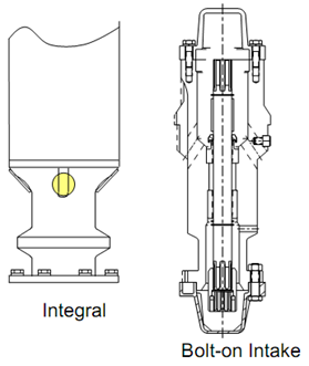
Usually, the pump intake is a separate component that bolts onto the bottom of the pump section. Occasionally, the pump is built in either a lower tandem or single configuration. In these cases, the pump intake as an integral part of the pump assembly.

Continue reading

Compression Pump vs. Floater Pump

There are mainly two designs of electrical submersible pump stages widely used by ESP’s service companies: 

  • Fixed impeller or compression pump design: every impeller is fixed to the shaft and is not free to move up and down. Hence, it cannot move without the shaft moving. All the impellers are “compressed” together to make one rigid body.
  • Floating stage design: each impeller in a floater pump is free to move up and down on the shaft within the confines of the diffuser as depicted in the following Figure. The thrust washers on the impeller support the stage thrust. The amount of thrust varies with liquid rate (the amount of fluid being pumped).

Continue reading

ESP: Pump Stage

A “ Pump Stage ” consists of an impeller, diffuser and thrust washers. As shown by the following figure, the impellers rotate with the shaft and spin at the RPM of the motor. The stationary diffusers turn the fluid into the next impeller and do not rotate. Pumps are assembled by stacking stages on a shaft and compressing the stack in a housing. A stage will produce a given amount of flow and lift (head) at the motor RPM.

Continue reading