Guides to Flowing Gradient Survey Data from API RP 11 V5

The purpose of this article is to present rough guides, or “rules of thumb”, to consider when preparing a Flowing Gradient Survey job program for gas lifted well. These recommendations will guide Production Engineers when preparing the survey instruments, planning the survey stop depths and times, when planning to obtain the bottomhole pressure data, as well as when preparing the job program for running pressure & temperature survey.


Preparing the survey instruments:

  • Run sinker bars as needed to overcome pressure surges when entering the wellhead from the lubricator.
  • Sampling rate should be at 30-second intervals.
  • Calibrate the electronic gauge with its software prior to each use.

Continue reading

Specific Gravity & API Gravity

A specific gravity scale developed by the American Petroleum Institute (API) for measuring the relative density of various petroleum liquids, expressed in degrees. API gravity is graduated in degrees on a hydrometer instrument and was designed so that most values would fall between 10° and 70° API gravity. The arbitrary formula used to obtain this effect is presented in the following paragraphs.

Specific Gravity (SG)

Specific gravity is a dimensionless value that compares all liquids to fresh water and all gases to air.  Certain liquid physical values can be calculated by multiplying the specific gravity of that liquid by the value for fresh water. For gases, the values are calculated by multiplying the specific gravity of the gas by the value for air. Freshwater and air have a specific gravity of one. Liquids and gases with a specific gravity greater than one are heavier than water or air.

API Gravity

Oil density is often reported in terms of API gravity. API gravity can be converted to specific gravity using the API to Specific Gravity Conversion equation, while specific gravity can be converted to API gravity using the Specific to API Gravity Conversion equation. Both equations are presented below:

API to Specific Gravity Conversion:

Specific to API Gravity Conversion:

Continue reading

Christmas Tree & Wellhead

A Christmas Tree comprises a series of valves, spools, a choke, and connection. It used for production or injection wells such as oil wells, gas wells, water injection wells, water disposal wells, etc. It provides a means of controlling the effluents, ensuring the safety of the facilities and giving measurement tools access to the well.

The Difference Between a Wellhead & Christmas Tree?

Many times, the words Christmas Tree and Wellhead are used interchangeably; however, a wellhead and Christmas tree are entirely separate pieces of well equipment. A wellhead must be present in order to utilize a Christmas tree and is used without a Christmas tree during drilling operations. Producing wells that require pumps, such as Sucher Rod Pumping Systems, frequently do not utilize any tree due to no pressure containment requirement.

Continue reading

Pressure drawdown & Skin Factor

Pressure Drawdown:

Pressure Drawdown (∆P) is defined as the difference between the static bottom hole pressure (SBHP) and the flowing bottom hole pressure (Pwf). Thus, the drawdown is the differential pressure that drives fluids from the reservoir into the wellbore.

∆P= Pressure drawdown = SBHP – Pwf

Example:

If SBHP = 200 bar, and Pwf  = 80 bar; therefore the Pressure drawdown (∆P) = 200 – 80 = 120 bar.

The amount of pressure drawdown dictates the amount of flow into the wellbore or production. The higher the pressure drawdown is, the higher the production rate. The drawdown, and therefore the production rate of a producing interval is typically controlled by surface chokes.

NB: Reservoir conditions, such as the tendency to produce sand, may limit the drawdown that may be safely applied during production before damage or unwanted sand production occurs.

Continue reading

Depth Calculations

In the oil and gas industry, depth in a well is the measurement, for any point in that well, of the distance between a reference point or elevation, and that point. It is the most common method of reference for locations in the well, and therefore, in oil industry speech, “depth” also refers to the location itself.

Because wells are not always drilled vertically, there may be two “depths” for every given point in a wellbore: the measured depth (MD) measured along the path of the borehole, and the true vertical depth (TVD), the absolute vertical distance between the datum and the point in the wellbore. In perfectly vertical wells, the TVD equals the MD; otherwise, the TVD is less than the MD measured from the same datum. Common datums used are ground level (GL), drilling rig floor (DF), rotary table (RT), kelly bushing (KB) and mean sea level (MSL). [1]

Terms and Abbreviations:

The common references used in operations include:

  • Kelly Bushing Height (KB): The height of the drilling floor above the ground level. Many wellbore depth measurements are taken from the Kelly Bushing. The Kelly bushing elevation is calculated by adding the ground level to the Kelly bushing height.
  • Rotary Table (RT): e.g. MDBRT or TVDBRT. MDBRT stands for Measured Depth Below Rotary Table (MDBRT),
  • Rig Floor (RF),
  • Driller’s Depth below rotary table (DDbrt): The depth of a well or features within the wellbore as measured while drilling. The measured length of each joint of drillpipe or tubing is added to provide a total depth or measurement to the point of interest. Drillers depth is the first depth measurement of a wellbore and is taken from the rotary table level on the rig floor. In most cases, subsequent depth measurements, such as those made during the well completion phase, are corrected to the wellhead datum that is based on drillers depth (reference: Schlumberger Oilfield Glossary).
  • Ground Level (GL),
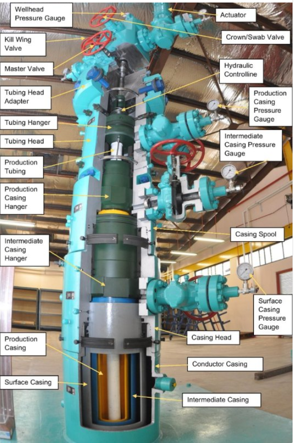
  • Casing Bowl Flange (CBF),
  • Tubing Hanger Flange (THF),
  • Mean Sea Level (MSL),
  • Subsea Level (SS),
  • Sea Bottom (SB),
  • Measured Depth (MD),
  • True Vertical Depth (TVD).

Continue reading