Casing Specifications

Casing is the major structural component of a well. It is a tubular steel product used to line the wellbore (maintain borehole stability), prevent contamination of water sands, isolate water from producing formations, and control well pressures during drilling, production, and workover operations. Casing provides locations for the installation of blowout preventers, wellhead equipment, production packers, and production tubing.

The cost of casing is a major part of the overall well cost, so the selection of casing size, grade, connectors, and setting depth is a primary engineering and economic consideration.

Casing Strings:

Since the well is normally drilled in segments, multiple concentric casing strings are usually installed in the well. There are six basic types of casing strings:

Continue reading

5 things you should know about the ISO 16530-1 Well Integrity Standard

By Mark Plummer MSc BEng, Passionate Drilling Engineer – Oil & Gas | Geothermal | HPHT | Well Abandonment (P&A) | Well Examiner

In March, 2017 ISO released their Latest Well Integrity Standard, ISO 16530-1: Life Cycle Governance. In this article I will provide the background to the standard and discuss some of the key sections contained within.

BACKGROUND TO ISO 16530-1

1. It was developed by producing operating companies for oil and gas, and is intended for use in the petroleum and natural gas industry worldwide

2. It is intended to provide guidance to the Well Operator on managing well integrity throughout the well life cycle. Furthermore, it addresses the minimum compliance requirements for the well operator to claim conformity with ISO 16530-1.

3. It provides recommendations and techniques that well operators can apply in a scalable manner, based on a well’s specific risk characteristics

4. ISO 16530-1 is intended to compliment the 2014 issued ISO 16530-2 Technical Standard (TS) – Well Integrity for the Operational Phase, which is intended to provide the requirements to manage Well Integrity during the operation (production) phase only.

5. The standard is not applicable to:

  • Well control activities implemented to prevent or mitigate unintentional release of formation fluids from the well to its surroundings.
  • Wellbore integrity, sometimes referred to as “borehole stability”

KEY SECTIONS OF ISO 16530-1

Continue reading

PVT Experiments: Separator Test

Separator Test experiments are carried out for both oil and gas condensate mixtures. A sample of reservoir liquid is placed in the laboratory cell and brought to reservoir temperature and bubble-point pressure. Then the liquid is expelled from the cell through a number of stages of separation.  Usually, two or three stages of separation are used, with the last stage at atmospheric pressure and near-ambient temperature (60 to 80°F).

The gas is let out of the separator through the top and is transferred to standard conditions, where its volume is measured. As for the differential liberation experiment, liquid dropping out from the gas is converted to an equivalent gas volume at standard conditions.

The liquid from the first separator is let into a second separator at a lower pressure and temperature than the first one. At which conditions, more gas will be liberated as sketched in the figure below. As with the gas from the first separator, this gas is transferred to standard conditions.

The oil remaining after gas removal is brought to the conditions of the next separator stage. The gas is removed again and quantified by moles and specific gravity. Oil volume is noted, and the process is repeated until stock-tank conditions are reached. Final oil volume, Vo, and specific gravity, SGo, are measured at 60°F.

Continue reading

PVT Experiments: Differential Liberation

The bubble point pressure is determined by an experiment called “Constant Composition Expansion” (CCE), also called: “flash liberation”. The device used to perform this experiment is the PV cell, as shown and described in the article “Constant Composition Expansion “. The Differential Liberation (DL), discussed in this article, is experimentally performed in a similar PV cell.

The main difference between these two types of experiments is that in the Constant Composition Expansion (or flash expansion) no gas is removed from the PV cell. But instead, the gas remains in equilibrium with the oil. As a result, the overall hydrocarbon composition in the cell remains unchanged.

In the differential liberation experiment, however, pressure gradually decreases in steps and any liberated gas is removed from the oil. All depletion stages are performed at the same reservoir temperature. Therefore, there is a continual compositional change in the PV cell, the remaining hydrocarbons becoming progressively richer in the heavier components, and the average molecular weight thus increasing.

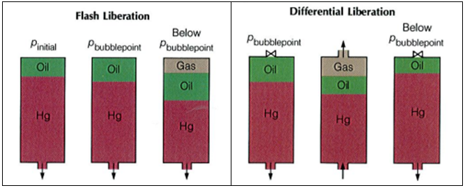
The differential liberation experiment starts at the bubble point pressure determined from the CCE (since above this pressure the flash and differential experiments are identical).

Example*:

The following example guides you on how to use and interpret the data from Differential Liberation test. The reservoir temperature is T= 200 °F and the bubble point pressure is 3330 psia.

The essential data obtained from the differential liberation experiment, performed on the same oil sample as CCE test, are listed in the following table:

Continue reading

Tubing Rotator reduces rod pumping failures

The tubing, in a well produces by the mean of a rod pumping system, represents the second largest investment in the well. Every day, every stroke on the pumping unit can cause wear in the tubing. On ever stroke the rods move up and down. Especially for deviated wells, the rods will always tend to lie on the downside of the tubing. So, on every stroke of the pumping unit, the rods are wearing a path into the metal of the tubing, path that will become a hole in the tubing.

Rod-wear track in tubing (from a 1” Spray-Metal coupling rubbing in 2 7/8” tubing)

Tubing Wear:

In a typical pumping well running at 10 strokes per minute, the rods will move against the tubing 14400 times every day. This wear will eventually cause a tubing failure. A common tubing failure is termed a “tubing split” and normally will be thin on one side of the tubing’s internal surface (about 20% of the tubing’s circumference) and can be detected by pinging with a hammer, cutting open the tubing, or running a thumb inside the tubing to feel for the thin area. The outside of the tubing will normally have a “tubing split” where a thin crack 1 to 5 inches long runs along the longitudinal axis of the tubing as shown in the following figure.

Continue reading