A good understanding of counterbalance is vital to the successful operation of surface sucker rod pumping units. Poor counterbalance practices can cause early failure of the gear reducer gearing and will result in excessive energy cost.
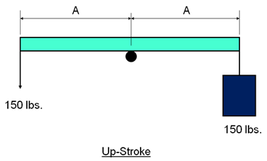
Non-counterbalanced lever system:
The up-stroke:
The figure above represents a simple non-counterbalanced lever system. On the up-stroke, by pulling down on the end of a beam, a man is lifting a bucket full of water having a combined weight of 150 lbs.
Note that the upstroke effort of the man is a substantial 150 lbs.
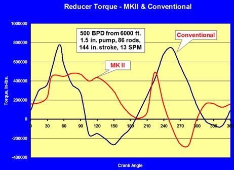
This article helps understand the difference between Conventional & Mark II pumping units in term of production performance. SROD, the predictive program from General Electric (GE), has been used in order to compare the Reducer Torque Performance, the Stroke Length, and the Polished Rod Velocity, of a conventional unit and a Mark II unit. In order to do that, production data from the well MF-1 are used.
MF-1 is an oil well activated using a sucker rod pump. The target rate is 500 BPD, the pump is set at 6000 ft, the plunger diameter is 1.5 inch, the rod string is 86, the stroke length is 144 inch and the pumping speed is 13 spm.
Reducer Torque:
Reducer Torque vs. Crank Angle:
SROD, the predictive program from GE, has been used in order to compare the reducer torque performance of a conventional unit and a Mark II unit. The plots “Torque (in in-lbs) versus the crank angle” are depicted in the following graph.
Note that the MKII does a better job approaching the uniform torque goal than the conventional unit and therefore haslower peak torque.
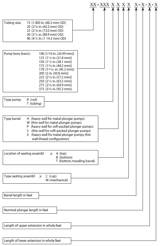
The pump designation is part of API Spec 11AX and describes the main specifications of an API subsurface pump. It is a nomenclature to classify API sucker rod pumps and tubing pumps according to their main characteristics. It is comprised of seven parts, separated by dashes. Example: 20-125-RHBC-10-4-2-2
Each part, in order, describes the following specifications:
Nominal tubing size (inch – given as a key representing the actual size)
Basic bore size (inch)
Type of pump, type of barrel, location and type of seating assembly (letter code)
Barrel length (ft)
Plunger length (ft)
Length of upper extension, used with heavy-wall barrel (inch)
Length of lower extension, used with heavy-wall barrel (inch)
Example: A 1 1⁄4 in. (31.8 mm) bore rod type pump with a 10 ft(3.048 m) heavy wall barrel and 2 ft (0.610 m) upper extension, 2ft (0.610 m) lower extension, a 4 ft (1.219 m) plunger, and a bottom cup type seating assembly for operation in 2 3⁄8 in.(60.3 mm) tubing, would be designated as follows:
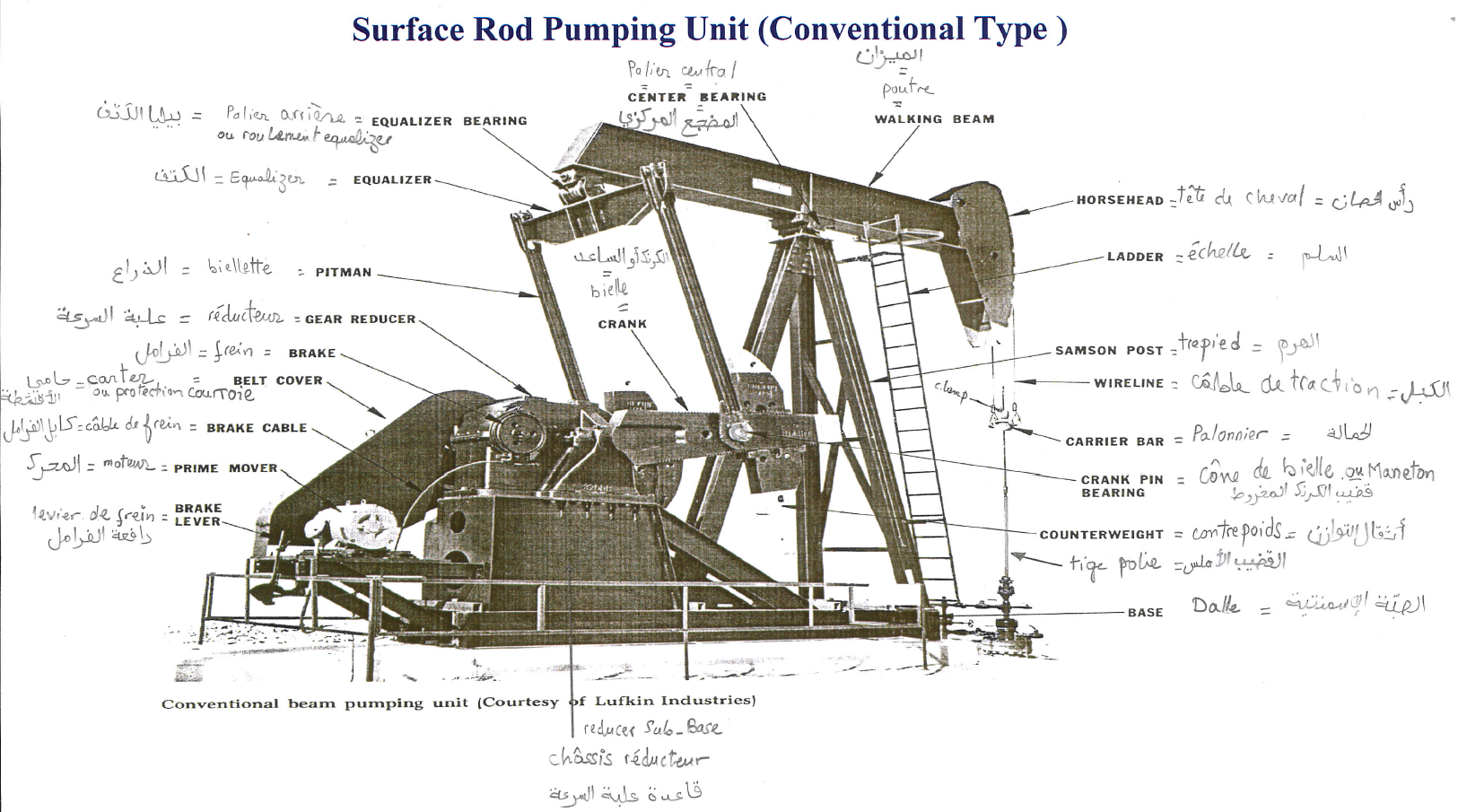
The working principle of a sucker rod pumping unit, as well as its components, have been detailed in a previous article titled: “Beam Pumping Unit Principles and Components”. This article will focus on the names of surface components of sucker rod pumps used in different languages, namely: Arabic, English, and French.
NB: As a reminder, beam pumping unit is a machine for translating rotary motion from a crankshaft to a linear reciprocating motion for the purpose of transferring mechanical power to a down-hole pump. The purpose, simply stated, of the basic system is to transmit energy from the surface to the downhole pump.
The conventional pumping unit is a modern version of the beam pumping unit first built in 1926 with the invention of crank counterbalance. It is a rear mounted class 1 lever system with crank counterbalance.
Typically, if one were to drop a plumb line off the equalizer bearing that line would fall over the center of the crankshaft. This machine can be rotated both Clockwise (CW) and Counterclockwise (CCW) with approximately the same performance characteristics.
It is manufactured in a wide variety of sizes and it can be fitted with many types of prime-mover bases that attach to the normal unit base.
This is the most common pumping unit type, because of its relative simplicity of operation, low maintenance requirements and adaptability to a wide range of field applications. As the cranks on a conventional unit rotate, the pitman side members cause the walking beam to pivot on a center bearing, moving the polished rod. Adjustable counterweights are located on the cranks.
As detailed by the article titled “Beam Pumping Unit Principles and Components“, most important parts of the conventional units are: Base, Counterweight, Crank, Samson Post, Horse Head, Walking Beam, Equalizer, Pitman, Gear Reducer, Brake and Prime Mover.