How Does Jet Pump Work?

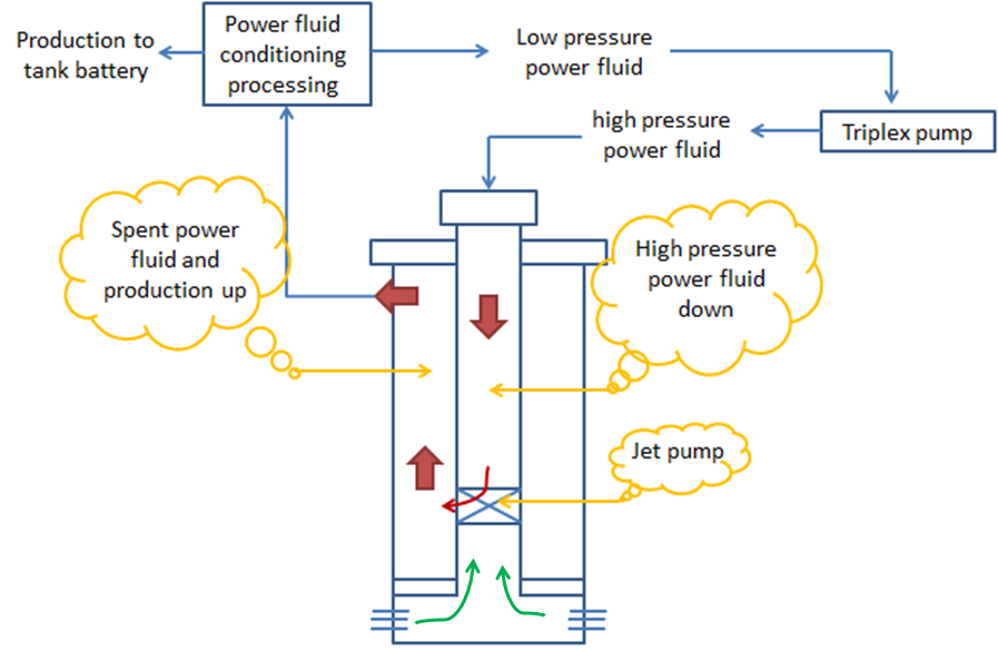
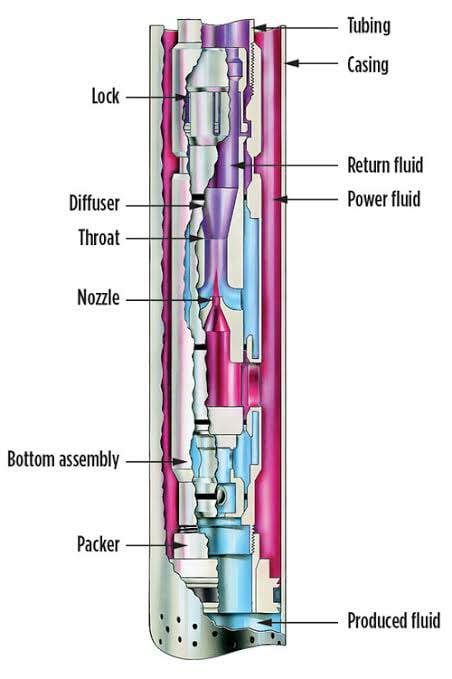
The jet pump operates by pumping power fluid at high pressure and rate from surface to activate/drive a downhole pump. Looking at the downhole jet pump, there are three main components:

  • Nozzle,
  • Throat,
  • And Diffuser.

The nozzle and throat are the key components of a jet pump. The ratio of the areas of these two parts is known as the area ratio of the pump and it determines the performance characteristics of the pump. Pumps with the same area ratio have the same performance and efficiency curves

Jet Pumps operates on Venturi principle. Above the JP, before entering the nozzle, the power fluid has high pressure (designated as PN) and low flow velocity.

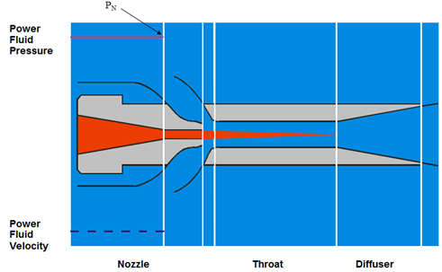
While the power fluid passes the nozzle, due to the decrease in flow area it is transformed from low velocity, high static pressure flow to a high velocity, low static pressure flow (PS). This creates a pressure drop below the nozzle which drives the reservoir fluids into the pump.

Continue reading

Jet Pumps Working Principle

The first consumer of water jets pump was James Thompson back in 1852. In 1870, J. M. Rankin introduced the theory of jet pump operation, afterward, a number of papers have been published to develop the technology. The work of Gasoline and O’Brien in 1933 is considered to be the standard reference work. It has been based on both theoretical and experimental results. Since that time, developments in the technology have continued to the point that today jet pumps have high operational flexibility.

What is Hydraulic Lift?

As a general description, Hydraulic Lift (Jet Pumps) represents pumping power fluid at high pressure and rate from surface to activate/drive a downhole pump. Power Fluid can be water or oil.

With Jet Pump applications the completion needs to have minimum 3 flowing conduits:

  1. A conduit for power fluid injection (inside of the tubing in case of standard flow, and in the annular space in case of reverse flow).
  2. For reservoir fluid flow (below the JP & packer).
  3. And a conduit for commingled fluid flow to the surface.


Jet Pump working principle:

The jet pump artificial lift system is composed of two principal parts: the surface pumping equipment and the downhole jet pump. In the surface, the reciprocating pump transfers energy to the fluid increases its pressure, drove through surface piping, production tubing (or annular space) until the jet pump, placed on the bottom.

Continue reading

Rod Rotator extends the life of rod-pumped wells

The constant up-and-down movement of a sucker rod creates excessive friction between rods and tubing which can result in premature rod and tubing failures due to excessive wear. If left unchecked, this generally requires a costly intervention to make repairs.

To extend the sucker rod run life, one of the widely used techniques is the use of rod rotators. A rod rotator is a mechanical device installed on the polished rod between the carrier and the polished rod clamp. It incrementally rotates the rod with each stroke. A rotating mechanism with an actuator lever arm is connected to the walking beam with a metal string. As the surface unit moves up and down, it pulls and releases this metal string so that, moves the actuator lever arm up and down. The rotation mechanism is activated and this slowly rotates the polished rod and the rod string below.

Continue reading

“Rocking” Gas-Lift Wells


The operation of ”rocking” a gas-lift well, also called: ”fluid level depressing”, is required to unload the well when the fluid column is heavier than the available lift pressure. Thus, the top gas lift valve cannot be uncovered with the available injection-gas pressure.

”Rocking” the well consists on applying an injection gas pressure simultaneously to the tubing and casing. The injected gas in the tubing will push the fluid column back into the formation; therefore reduce height, thus the weight of the fluids being lifted and allow unloading with the available lift pressure.

The tubing pressure is released rapidly, and the source of the major portion of the fluid entering the tubing is load fluid from the annulus. This procedure may be required several times to lower the fluid level in the casing annulus below the depth of the top gas lift valve.

PS: Several hours may be required to ”rock” a well having low reservoir permeability.

”Rocking” Procedure:

Continue reading

Gas Lift Instability

By Burney Waring, Consultant at WaringWorld, Inc.

Someone asked me recently about gas lift well instability. This is how I learned to determine if gas lift will be unstable, that is deciding if the well will exhibit casing heading.

As far as I know, this was invented by Dick ter Avest with Shell in 1995, but I think Wim der Kinderen was finally able to explain it to me so I could understand it.

Continue reading