Tubing Rotator reduces rod pumping failures

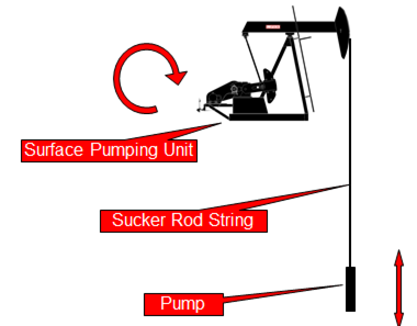
The tubing, in a well produces by the mean of a rod pumping system, represents the second largest investment in the well. Every day, every stroke on the pumping unit can cause wear in the tubing. On ever stroke the rods move up and down. Especially for deviated wells, the rods will always tend to lie on the downside of the tubing. So, on every stroke of the pumping unit, the rods are wearing a path into the metal of the tubing, path that will become a hole in the tubing.

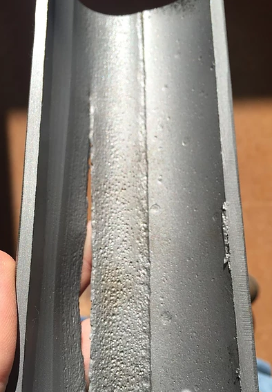
Rod-wear track in tubing (from a 1” Spray-Metal coupling rubbing in 2 7/8” tubing)

Tubing Wear:

In a typical pumping well running at 10 strokes per minute, the rods will move against the tubing 14400 times every day. This wear will eventually cause a tubing failure. A common tubing failure is termed a “tubing split” and normally will be thin on one side of the tubing’s internal surface (about 20% of the tubing’s circumference) and can be detected by pinging with a hammer, cutting open the tubing, or running a thumb inside the tubing to feel for the thin area. The outside of the tubing will normally have a “tubing split” where a thin crack 1 to 5 inches long runs along the longitudinal axis of the tubing as shown in the following figure.

Continue reading

Effect of CO2 on downhole flowrate calculation

Downhole flow rate can be calculated from surface flow rate (stock tank barrels) using the following equation. It is assumed that no gas is dissolved in the water phase and the water formation volume factor is equal to one.

Downhole flow rate = [(Oil rate)sc × Bo] + [(Free GOR) × (Oil rate)sc × Gas FVF] + (Water rate)sc

Free GOR = Producing GOR – Solution GOR, therefore:

q = ( Qo × Bo ) + [ ( R – Rs) × Qo × Bg × 1000] + Qw

Where:

  • q = downhole flow rate (bbl/d or m3/d)
  • Qo = Oil flow rate at standard conditions (stb/d or m3sc/d)
  • Bo = Oil formation volume factor (bbl/stb or m3sc/m3sc)
  • R = Producing gas-oil ratio (scf/stb or m3sc/m3sc)
  • Rs = Solution gas-oil ration (scf/stb or m3sc/m3sc)
  • Bg = Gas formation vol. factor (bbl/mscf or m3sc/m3sc)
  • Qw = Water flow rate at standard conditions (stb/d or m3sc/d)

Effect of CO2 on downhole flowrate calculation:

If CO2 is present, the calculation of downhole flow rate becomes more complex for many reasons:

Continue reading

ESP Design – Hand Calculations

This article walks through the suggested nine step procedure for selecting and designing an electric submersible pump. This nine step procedure for ESP design is a basic hand-design of simple water and light crude oil. For more complicated well conditions, such as high GOR, viscous oil, high-temperature wells, etc. a number of computer programs are available to automate this process.

Step 1: Basic Data:

As detailed in the article “Step 1: Basic data ”, step 1 of the nine step design procedure is the most important step because all the others design steps will depend on the basic data selected in this step.

In this example, a high water cut well is considered. This is the simplest type of well for sizing submersible equipment.

  • Well Profile:

Vertical Well

Casing: 7” 26#

Tubing: 3 ½” 9,2# N80 NU

Top perforation: 2003m

Pump Intake depth: 1713m

Continue reading

Why Rod Lift?

Rod Pumping System is a system of artificial lift using a surface pumping unit to impart reciprocating motion to a string of rods. Rod string then extends to a positive displacement pump placed in well near producing formation. In other words, the primary function of a rod pumping system is to convert the energy supplied at the prime mover into the reciprocating motion of the pumping unit required to transmit energy through the rod pumping to the downhole pump in order to artificially lift the reservoir.

Rod Pumping System:

The rod pumping system is made up of three components:

  • The surface pumping unit: which provides the means of turning the rotating power and motion of the motor into the reciprocating motion at the correct speed needed at the pump.
  • The rod string: that connects the surface unit to the pump and provides the force at the pump to lift the fluid to the surface.
  • The pump: which pumps the fluid to the surface.

The integrity of this pumping system is only as good as each of the links or components.

Continue reading

Torque and Maximum Counterbalance Moment

Torque is defined as twisting force. To calculate the torque around the rotation of a crank caused by a weight at the end of the crank, you need to multiply the weight times the horizontal distance from the center of gravity of the weight to point of rotation.

Unit of Torque:

The International System of Units, SI, (the French Système International (d’unités)), suggests using the unit newton meter (N⋅m). The unit newton meter is properly denoted N⋅m or N m. This avoids ambiguity with mN (millinewtons).

In Imperial units, “pound-force-feet” (lbf-ft), “foot-pounds-force”, “inch-pounds-force” are used. Other non-SI units of torque include “meter-kilograms-force” are also used. For all these units, the word “force” is often left out. For example, abbreviating “pound-force-foot” to simply “pound-foot” (in this case, it would be implicit that the “pound” is pound-force and not pound-mass).

Maximum and Minimum Counterbalance Moment:

The crank generates maximum torque when it is in a horizontal position. This maximum torque is known as the Maximum Counterbalance Moment” ( maximum CBM) expressed in inch-pounds.

NB: In rod pumping, the CBM is expressed in thousands of inch pounds.

Continue reading