By Burney Waring, Consultant at WaringWorld, Inc.
Someone asked me recently about gas lift well instability. This is how I learned to determine if gas lift will be unstable, that is deciding if the well will exhibit casing heading.

As far as I know, this was invented by Dick ter Avest with Shell in 1995, but I think Wim der Kinderen was finally able to explain it to me so I could understand it.
This technique was included in WinGLUE software and was a great, simple predictor in the analysis of many hundreds of gas lift wells.
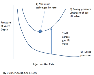
Follow the sequence 1-3 to calculated casing pressure at the valve depth vs injection gas rate.
1) Can be calculated with multiphase well performance software and should be a system (inflow and outflow and choke, if any) calculation. For each injection rate, find the pressure at the lift depth in the tubing.
2) Calculate the dP across the gas lift valve port (or choke, if installed) versus injection rate. For this purpose, Thornhill-Craver will work well in most cases, especially if operating off of a simple orifice valve.
3) Add 1) and 2) to get 3).
4) Find the minimum.
Left of the minimum pressure the rates are unstable. If a rate below that rate is injected, the injection gas will be injected, then deplete the annulus until the production pressure is more than the injection pressure. Then it will build up until it can inject again, starting the heading cycle again. If you have it on a rate controller, the rate will average correctly (maybe) but it will be intermitting unintentionally, i.e. casing heading.
Larger valves will have a lower dP across the valve and so the minimum will shift to the right, to higher lift gas rates.
This means that most wells that do not produce on their own have an operational range. The low end is explained above. The right side of the curve will rise with injection rate until either a) the maximum injection pressure at the surface is reached, or b) until the pressure re-opens a gas lift valve uphole, which will also cause instability (because now the gas lift rate through one or both valves may fall below the minimum).
Addendum:
By ‘larger valves’ I mean a larger diameter port or a larger diameter choke. This would also be the case of a hole (or holes) in the tubing. Or, multiple open valves. All of these would serve to reduce the pressure differential between the casing and tubing, and also reduce the slope of the casing pressure curve (3) in the graph.


I remember working with some of Burney’s gas lift programs for Shell SMI 130 fields. Very exciting work!!!